
Page 171 - IJB-9-2
P. 171
International Journal of Bioprinting 3D Printing Multifunctional Orthopedic Biocoatings
A B
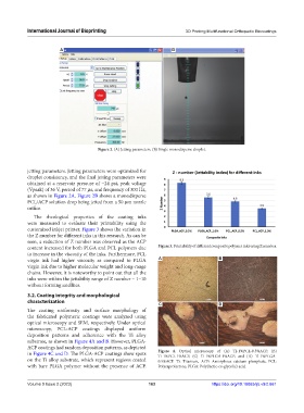
Figure 2. (A) Jetting parameters. (B) Single monodisperse droplet.
jetting parameters. Jetting parameters were optimized for
droplet consistency, and the final jetting parameters were
obtained at a reservoir pressure of −24 psi, peak voltage
(Vpeak) of 36 V, period of 77 µs, and frequency of 300 Hz,
as shown in Figure 2A. Figure 2B shows a monodisperse
PCL/ACP solution drop being jetted from a 50 µm nozzle
orifice.
The rheological properties of the coating inks
were measured to evaluate their printability using the
customized inkjet printer. Figure 3 shows the variation in
the Z number for different inks in this research. As can be
seen, a reduction of Z number was observed as the ACP
content increased for both PLGA and PCL polymers due Figure 3. Printability of different composite polymer inks using Z number.
to increase in the viscosity of the inks. Furthermore, PCL
virgin ink had higher viscosity as compared to PLGA A B
virgin ink due to higher molecular weight and long-range
chains. However, it is noteworthy to point out that all the
inks were within the jettability range of Z number – 1–10
without forming satellites.
3.2. Coating integrity and morphological
characterization
C D
The coating uniformity and surface morphology of
the fabricated polymeric coatings were analyzed using
optical microscopy and SEM, respectively. Under optical
microscopy, PCL-ACP coatings displayed uniform
deposition patterns and adherence with the Ti alloy
substrate, as shown in Figure 4A and B. However, PLGA-
ACP coatings had random deposition patterns, as depicted
in Figure 4C and D. The PLGA-ACP coatings show spots Figure 4. Optical microscopy of (A) Ti-1%PCL-0.5%ACP, (B)
Ti-1%PCL-1%ACP, (C) Ti-1%PLGA-1%ACP, and (D) Ti-1%PLGA-
on the Ti alloy substrate, which represent regions coated 0.5%ACP. Ti: Titanium, ACP: Amorphous calcium phosphate, PCL:
with bare PLGA polymer without the presence of ACP. Polycaprolactone, PLGA: Poly(lactic-co-glycolic) acid.
Volume 9 Issue 2 (2023) 163 https://doi.org/10.18063/ijb.v9i2.661