
Page 316 - IJB-9-2
P. 316
International Journal of Bioprinting Flexible 3D printing in cardiovascular medicine
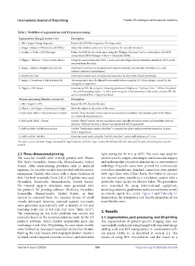
Table 2. Workflow of segmentation and 3D post-processing
Segmentation (ImageJ, version 1.53) Description
1. File → Import Image Sequence Import the DICOM images as a 2D image stack.
2. Image → Adjust → Window/Level (W&L) Adjust the window and level to be focused on the vascular structures.
3. Analyze → Tools → ROI Manager Define the ROI for the whole stack using the “Polygon Selection” tool in combination with ROI
interpolation (ROI Manager → More → Interpolate ROIs).
4. Plugins → Macros → Clear Outside Macro Using the macro defined in Table 1, bones and other high-density structures outside the ROI can be
removed from the stack.
5. Image → Adjust → Brightness/Contrast (Optional) Contrast can be improved to remove residual non-vascular structures (i.e., early
contrast-enhanced parenchyma).
6. Paintbrush Tool (Optional) Remove non-vascular structures slice-by-slice with a black paintbrush.
7. Image → Transform → Flip Horizontally The image stack has to be flipped horizontally before using the 3D Viewer plugin, caused by the
triangulation algorithm.
8. Plugins → 3D Viewer Generate an STL file using the following parameters: Display as = Surface, Color = White, Threshold
= 50, and Resampling factor = 2. After confirming the 8-bit conversion of the stack, a binary STL file
can be exported (File → Export surfaces).
3D post-processing (Blender, version 3.0) Description
1. File → Import → STL Import the STL file into Blender.
2. Object → Set Origin → Geometry to Origin Move the object to the center of the scene.
3. Edit mode: Select → Select Linked → Linked Use the “Select Linked” tool to remove unconnected (unlinked) non-vascular parts of the object
(i.e., residuals of parenchyma).
4. Edit mode: Mesh → Bisect Use the “Bisect” tool to cut the vasculature open (usually, at least the aorta and procedure relevant
arteries). Without this step, a closed vascular model will be generated.
5. Add modifier: Subdivision surface Use the “Subdivision Surface Modifier” to smooth the object and prevent the formation of steps
from triangulation.
6. Add modifier: Solidify Generate vessel walls using the “Solidify Modifier” with a wall thickness of 1 mm.
The open-source software ImageJ was used for segmentation, while the open-source 3D software Blender was used for post-processing the vascular
models.
2.3. Three-dimensional printing light curing for 10 min at 60°C. The resin was used for
The vascular models were initially printed with Elastic patient-specific surgery planning in cardiovascular surgery
50A Resin (Formlabs, Somerville, Massachusetts, United and endovascular procedure simulations in interventional
States). After encountering problems such as material radiology. If specific cases were printed for endovascular
ruptures, the vascular models were printed with the newer, procedure simulations, standard connectors were printed
transparent Flexible 80A Resin with a shore hardness of with rigid clear resin (Clear Resin, Formlabs) to connect
80A. For both materials, Form 3 SLA 3D printer was used the visceral artery models to a circulatory system with a
(Formlabs, Somerville, Massachusetts, United States). peristaltic water pump via silicone tubes. The procedures
No internal support structures were generated with were simulated by using interventional equipment,
the printer’s 3D printing software (PreForm, Formlabs, including catheters, guidewires, and microcatheters, as well
Somerville, Massachusetts, United States), as they as embolic agents (i.e., coils). Figure 1 and Videoclip S1
cannot be removed from the vascular lumen of small demonstrate the transparent and flexible properties of the
vessels afterward; however, external support structures novel flexible resin.
were generated automatically with a density of 0.8 and
touching point size of 0.4 mm (raft type: “mini rafts”). 3. Results
The positioning on the build platform was carried out
manually based on the recommendations made by the 3D 3.1. Segmentation, post-processing, and 3D printing
printer’s software, which marked unprintable parts like The segmentation of patient-specific imaging data was
overhangs in red. After 3D printing, the case-based models successfully performed using ImageJ with standard image
were finished by cleaning in isopropyl-alcohol for 10 min, editing tools and ROI interpolation in combination with
flushing the small vessels with isopropyl-alcohol injection the macro (Table 1), as described in section 2.2. The
by hand, careful support structure removal, and ultraviolet results of using ROI interpolation and the macro in a
Volume 9 Issue 2 (2023) 308 https://doi.org/10.18063/ijb.v9i2.669