
Page 38 - IJB-9-2
P. 38
International Journal of Bioprinting Scaffolds printed with light sheet stereolithography
A C
B
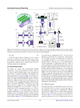
Figure 1. (A) Local illumination of a light sheet in a bottom-up 3D printer configuration. (B) Generation of light sheet-based optical system with two planes
of symmetry. (C) Schematic of the built light sheet SLA device. M: Mirror; S: Mechanical shutter; BS: Beam shaper; DF: Dichroic filter; CL: Cylindrical lens;
GM: Galvano mirror scanner; SL: Scan lens; TL: Tube lens; LS-LSA: Light sheet stereolithography.
M =f /f (2) by combining one cylindrical lens (EFL = 50 mm) and the
YZ sl cl
In the first approximation, Equations 1 and 2 help to telecentric scan lens (CLS-SL, Thorlabs Inc., United States).
determine the proper characteristics of the lenses needed The two-plane symmetry introduced by the cylindrical
in the system. In addition, the scan lens combined with lens elongates the beam in one orientation (y-axis) and
a mechanical Galvano mirror scanner steers the LS in focuses the beam in the other one (x-axis), which results in
different positions of the film plane. LSs with large length-to-width aspect ratios (l/w~1100). To
produce the patterns on the bottom surface of the resin vat
2.2. Demonstrator device along the complete field of view (FOV) of the scan lens, two
We proved our concept with commercially available Galvano mirrors (GVS202, Thorlabs Inc.) were positioned
components. Only few mechanical elements, such as near the front focal point of the scan lens. The rotational
the resin vat and the build support, were customized in angles of the Galvano mirrors expose the resin at different
our facilities. A complete schematic of the designed and positions along the resin plane with an exposure time
implemented system is shown in Figure 1C. First, the laser controlled by the mechanical shutter (beam shutter). All
source (405 nm) is propagated through a power attenuator the opto-electro-mechanical components were controlled
system (λ/2-plate and polarized beam-splitter, P-BS) to by an application we developed in the software LabView,
control the radiant exposure of the printing process. The which is interfaced with a data acquisition device (National
laser beam is then propagated through a beam expander Instruments, United States).
and an irradiance distribution conditioner, the beam 2.2.1. Alignment system
shaper. The latter consists of two cylindrical lenses with
effective focal length EFL = 25 mm and EFL = 125 mm. In The alignment of the LS on the bottom surface of the resin
combination with the rectangular aperture A (4 × 20 mm² vat takes place before starting the structuring sequence.
at plane A, Figure 1C), the beam shaper converts the The alignment is performed by collecting the reflected
Gaussian distribution of the laser beam into a uniform light from the FEP film with the scan lens and focusing the
irradiance with a rectangular boundary, which is used to light back on a CMOS sensor, as shown in the calibration
produce the LS with uniform illumination at the FEP film system of Figure 1C. The LS produced on the sensor is a
(resin vat plane, Figure 1C). The LS illumination is achieved magnified image of the LS used to illuminate the resin vat.
Volume 9 Issue 2 (2023) 30 https://doi.org/10.18063/ijb.v9i2.650