
Page 40 - IJB-9-2
P. 40
International Journal of Bioprinting Scaffolds printed with light sheet stereolithography
A C
B
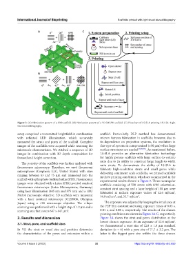
Figure 2. (A) Fabrication pattern of a 0/90 scaffold. (B) Fabrication pattern of a 3D 0/45/90 scaffold. (C) Flowchart of LS-SLA printing. LS-LSA: Light
sheet stereolithography.
setup comprised a transmitted brightfield in combination scaffold. Particularly, DLP method has demonstrated
with reflected LED illumination, which accurately micron features fabrication in scaffolds; however, due to
measured the struts and pores of the scaffold. Complete its dependence on projection systems, the resolution in
images of the scaffolds were acquired while retaining the this type of systems is compromised (≥50 μm) when large
microscale characteristics. We stitched a sequence of 2D surface structures are needed [39,54,55] . As mentioned before,
images in combination with 3D depth composition for LS-SLA provides an alternative fabrication technology
focused and height correction. for highly porous scaffolds with large surface-to-volume
ratio due to its ability to construct large length-to-width
The porosity of the scaffolds was further analyzed with
fluorescence microscopy. Therefore, we used fluorescent ratio struts. To demonstrate the ability of LS-SLA to
fabricate high-resolution struts and small pores while
microspheres (Cospheric LLC, United States) with sizes delivering centimeter scale scaffolds, we printed scaffolds
ranging between 63 and 75 μm and immersed into the in three printing conditions, which are summarized in the
scaffold with a phosphate-buffered saline (PBS). Fluorescence experimental results shown in Figure 3. Three rectangular
images were obtained with a Leica SP8X inverted confocal scaffolds consisting of 500 struts with 0/90 orientation,
fluorescence microscope (Leica Microsystems, Germany) constant strut spacing and a layer height of 100 μm were
using laser illumination (405 nm and 575 nm) and a 10X/ fabricated at radiant exposure values of 12.6 mJ/cm ,
2
NA0.4 microscope objective. 3D scaffolds were measured 16.9 mJ/cm , and 33.7 mJ/cm .
2
2
with a laser confocal microscope (OLS5000, Olympus,
Japan) using a ×20 microscope objective. The z-layer The exposure was adjusted by keeping the irradiance at
scanning was performed with a height step of 1.2 μm and a the FEP film constant and using exposure times of 0.03 s,
scanning area that covers 647 × 647 μm . 0.04 s, and 0.08 s, respectively. The results of the chosen
2
printing conditions are shown in Figure 3A-C, respectively.
3. Results and discussion Figure 3A shows the strut and pores distribution at the
lowest chosen exposure. At an exposure of 12.6 mJ/cm ,
2
3.1. Strut, pore, and scaffold sizes
we demonstrated a strut size of 12.8 ± 1.8 μm standard
In VP, the strut or voxel size and position determine deviation (n = 6) with a pore size of 71.7 ± 3.2 μm. The
the characteristics of the pores and extension within a latter is the biggest pore size within the three chosen
Volume 9 Issue 2 (2023) 32 https://doi.org/10.18063/ijb.v9i2.650