
Page 41 - IJB-9-2
P. 41
International Journal of Bioprinting Scaffolds printed with light sheet stereolithography
A
D
B
C
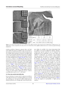
Figure 3. (A-C) Microscope images of the built scaffolds at three different exposure values show the size and distribution of strut and pore. The
square shows a zoom-in region from the same pictures. (D) Overall view of the complete scaffold shown in (C). Fractures are generated during
manipulation.
printing conditions. Exposure, exposure time, and laser size within the scaffold. It has been demonstrated that
power define the printing conditions that can be tuned in the scaffold can be functionalized for different cell types.
our system to modify the strut size and the printing time of Furthermore, specific properties can be improved by
the scaffold. Balancing those parameters can significantly modifying the size distribution of the pores within the
reduce the printing time and deliver the greatest throughput scaffold . Furthermore, the precision of the available
[27]
in terms of resolution and precision. For example, the strut scanning systems has greatly increased, which benefits
size of the scaffolds shown in Figure 3B and C was increased scaffold fabrication in pore size control and uniformity.
up to 43.4 ± 1.9 μm (n = 6), inducing the reduction of the To illustrate, we fabricated two scaffolds of different
pore size down to 36.2±1.5 μm at a constant strut spacing. strut spacing. Figure 4A shows the fluorescence image of
Furthermore, structures built with LS-SLA depict large a scaffold with a pore size of 68 ± 2.5 μm (n = 11), and
surface fabrication. Two-D stitched images of the scaffolds Figure 4B shows the scaffold that exhibits a pore size of
shown in Figure 3 demonstrate that LS-SLA can build 149.9 ± 2.3 μm (n = 10). Microspheres (diameter ranging
structures of large area and simultaneously conserves from 63 μm to 75 μm) were pipetted with PBS within both
microscale struts (<50 μm). Figure 3D shows a 2D stitched scaffolds and imaged with fluorescence microscopy as
image of the scaffold shown in Figure 3C with a measured depicted by the red circles in Figure 4. The microspheres
area of 19.09 mm × 18.83 mm. At the smallest strut size, stress the porous characteristics of the scaffolds fabricated
12.8 μm, the strut length-to-width ratio was l/w = 1696 for with LS-μ-SL. On one side, the microspheres were filtered
a scaffold with an area of 21.37 × 20.59 mm². out or kept in suspension by the small pores of the
scaffold (Figure 4A). On the other side, the microspheres
3.2. Pore size control and uniformity flowed within the pores of the scaffold since the pore size
In practical terms, it is easier to fix the exposure conditions was ≈ 2 times larger than the diameter of the microspheres
with respect to the desired resolution and steer the LS along in (Figure 4B). In general, the results presented in Figure 4
the scanning area. Steering the LS allows illuminating at mimic the property of permeability in highly porous
different positions and consequently controlling the pore scaffolds.
Volume 9 Issue 2 (2023) 33 https://doi.org/10.18063/ijb.v9i2.650