
Page 390 - IJB-9-2
P. 390
International Journal of Bioprinting In situ 3D bioprinter for skin wound healing
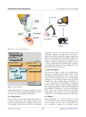
Figure 1. Scheme of in situ bioprinting system.
temperature is above 10°C. Since the operating room
usually has a temperature of about 20°C, it is necessary to
ensure the material is cooled in the syringe. A metal part is
adjacent to the cooling side, which provides cooling of the
syringe. A radiator was attached to the heated side of the
module for rapid heat outflow, and a cooling fan was used
to improve the heat sink. All components were attached to
the housing, which reduced the heat exchange of the metal
part with the external environment.
2.3. Electrical diagram
The provision of digital control of the cooling system
was carried out using the Cytron MD13S driver (Cytron
Technologies Sdn Bhd, Malaysia), which is able to control
devices with the necessary power. In the cooling system,
a voltage of 6V was used for cooling, while the current
consumption of the cooling system corresponds to 1
A. The LM2596S-ADJ (Semiconductor Components
Industries, USA) boards were used as voltage converters in
Figure 2. Design of in situ head. electrical coupling, which not only lowered the voltage but
also stabilized it. A voltage of 9 V was used for the stepper
and the TMC2100 driver (Trinamic, Germany) was used to driver and 6 V for the Peltier module. For the general
control it. The Arduino programming platform was used power supply of the system, a DC power supply with a
as a microcontroller controlling the end effector. voltage of 12 V and a maximum current of 2 A were used.
2.2. Cooling system 2.4. Software
The end effector uses a syringe cooling system based on When bioprinting, it is important that the robot’s
a Peltier module, which, when voltage is applied to it, movements and the volume of the material being squeezed
cools one side and heats the other (Figure 3). The material out are consistent with each other. Special software has
to be printed is polymerized (stitched) if the ambient been developed to implement this condition. Special
Volume 9 Issue 2 (2023) 382 https://doi.org/10.18063/ijb.v9i2.675