
Page 419 - IJB-9-2
P. 419
International Journal of Bioprinting Design and 3D printing of TPMS breast scaffolds
A
B C
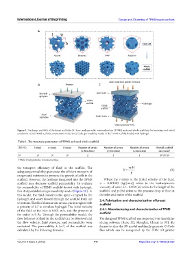
Figure 2. The design and FEA of the breast scaffolds: (A) Four triply periodic minimal surface (TPMS) units and whole scaffolds; the boundary and initial
conditions of (B) TPMS scaffold compression model and (C) the permeability model of the TPMS scaffold loaded with hydrogel.
Table 1. The structure parameters of TPMS unit and whole scaffold
RD (%) l (mm) w (mm) h (mm) Number of arrays Number of arrays Number of arrays Overall scaffold
(x direction) (y direction) (z direction) size (mm )
3
30 10 10 10 2 2 2 20*20*20
TPMS: Triply periodic minimal surface
the transport efficiency of fluid in the scaffold. The k = νυ H
adequate permeability guarantees the efficient transport of p (X)
oxygen and nutrients to promote the growth of cells in the
scaffold. However, the hydrogel integrated into the TPMS Where the ν refers to the initial velocity of the fluid,
scaffold may decrease scaffold permeability. To evaluate υ = 0.001003 (kg/[m.s]) refers to the hydrodynamic
the permeability of TPMS scaffold loaded with hydrogel, viscosity of water, H = 0.002 (m) refers to the height of the
this study established a permeability model (Figure 2C). In scaffold, and p (Pa) refers to the pressure drop of fluid at
this model, the fluid domain is the space occupied by the the inlet and outlet of the scaffold.
hydrogel, and water flowed through the scaffold from top 2.4. Fabrication and characterization of breast
to bottom. The fluid domain was set as a porous region with scaffold
a porosity of 0.7 to simulate hydrogel. The initial velocity
of the fluid at the inlet is 0.001 m/s, and the pressure at 2.4.1. Manufacturing and characterization of TPMS
the outlet is 0 Pa. Through the permeability model, the scaffold
flow behavior of fluid in the scaffold can be observed and The designed TPMS scaffold was imported into ideaMaker
the flow velocity, fluid pressure, and permeability were slicing software (Raise 3D, Shanghai, China) in STL file
evaluated. The permeability k (m ) of the scaffold was format to slice the 3D model and finally generate G-Code
2
calculated by the following formula: files which can be recognized by the FDM 3D printer
Volume 9 Issue 2 (2023) 411 https://doi.org/10.18063/ijb.685