
Page 418 - IJB-9-2
P. 418
International Journal of Bioprinting Design and 3D printing of TPMS breast scaffolds
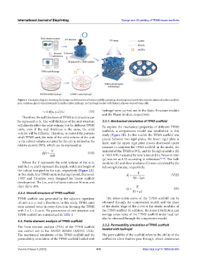
Figure 1. Schematic diagram depicting the design and fabrication of breast scaffold consisting of polycaprolactone triply periodic minimal surface scaffold,
poly (ethylene glycol) diacrylate/gelatin methacrylate hydrogel, and hydrogel loaded with human adipose-derived stem cells.
−≤ (x yz ,, ) ≤ c (VI) hydrogel were carried out in the Static Structure module
c
and the Fluent module, respectively.
Therefore, the wall thickness of TPMS unit structure can
be expressed as 2c. The wall thickness of the unit structure 2.3.1. Mechanical simulation of TPMS scaffold
will directly affect the solid volume, but for different TPMS To explore the mechanical properties of different TPMS
units, even if the wall thickness is the same, the solid scaffolds, a compression model was established in this
volume will be different. Therefore, to control the porosity study (Figure 2B). In this model, the TPMS scaffold was
of all TPMS unit, the ratio of the solid volume of the unit placed between two rigid plates, the lower rigid plate is
to the cuboid volume occupied by the unit is defined as the fixed, and the upper rigid plate moves downward under
relative density (RD), which can be expressed as: pressure to compress the TPMS scaffold. In the model, the
V material of the TPMS is PCL, and its Young’s modulus (E)
RD = (VII)
lwh is 199.9 MPa measured by tensile test and its Poisson’s ratio
(µ) was set as 0.35 according to references [44-46] . The bulk
Where the V represents the solid volume of the unit, modulus (K) and shear modulus (G) were calculated by the
and the l, w, and h represent the length, width and height of following formulae, respectively:
the cuboid occupied by the unit, respectively (Figure 2A).
In this study, four TPMS units including Gyroid, Diamond, K = E (VIII)
I-WP and Primitive were designed for breast scaffold 31 ( − 2 )µ
development. The l, w, and h of these units are 10 mm, and
their RD is 30%. E
G = (IX)
2.2.2. Overall structure of TPMS scaffold 21 ( + )µ
TPMS scaffold was generated by the adjacent repetition The stress-strain curve of the TPMS scaffold can be
of unit in x, y, and z directions. In this study, TPMS units obtained through the compression model, and the slope
were arrayed twice in every direction, forming the TPMS of the elastic stage of the curve is the elastic modulus of
with 2 × 2 × 2 units. The parameters of unit structure and the TPMS scaffold. In addition, the stress distribution and
TPMS scaffold are summarized in Table 1. average stress value of the TPMS scaffold under load can
also be obtained through the compression model.
2.3. Finite element analysis of TPMS scaffold
2.3.2. Permeability simulation of TPMS scaffold
The finite element analysis (FEA) of the TPMS scaffold
was carried out in the ANSYS 2021R1 (ANSYS, USA). loaded with hydrogel
The mechanical simulation of the TPMS scaffold and the The permeability of the scaffold refers to the ability of the
permeability simulation of the TPMS scaffold loaded with scaffold to allow fluid to pass through, which determines
Volume 9 Issue 2 (2023) 410 https://doi.org/10.18063/ijb.685