
Page 143 - IJB-9-3
P. 143
International Journal of Bioprinting Bioprinting tissue-engineered bone-periosteum biphasic complex.
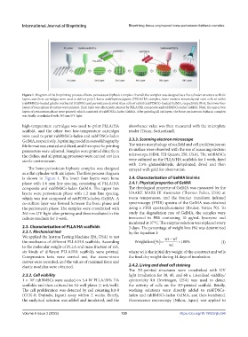
Figure 1. Diagram of the bioprinting process of bone-periosteum biphasic complex. Overall, the complex was designed as a flat cylinder structure with six
layers, and three cartridges were used to deliver poly-L-lactic acid/hydroxyapatite (PLLA/HA) complex, bone marrow mesenchymal stem cells of rabbit
(rabBMSCs)-loaded gelatin methacryl (GelMA) and periosteum-derived stem cells of rabbit (rabPDSCs)-loaded GelMA, respectively. First, the lower four
layers of bone phase structure were printed. Each layer was alternately printed by PLLA/HA composite and rabBMSCs-laden GelMA. Next, the upper two
layers of periosteum phase were printed, which consisted of rabPDSCs-laden GelMA. After printing all six layers, the bone-periosteum biphasic complex
was finally crosslinked with 365 nm UV light.
high-temperature cartridges was used to print PLLA/HA absorbance value was then measured with the microplate
scaffold, and the other two low-temperature cartridges reader (Tecan, Switzerland).
were used to print rabBMSCs-laden and rabPDSCs-laden
GelMA, respectively. A printing model in stereolithography 2.3.3. Scanning electron microscope
file format was created and sliced, and then specific printing The micro morphology of scaffold and cell proliferation on
parameters were adjusted. Samples were printed directly in its surface were observed with the use of scanning electron
the dishes, and all printing processes were carried out in a microscope (SEM; FEI Quanta 250, USA). The rabBMSCs
sterile environment. were cultured on the PLLA/HA scaffolds for 1 week, fixed
with 2.5% glutaraldehyde, dehydrated, dried and then
The bone-periosteum biphasic complex was designed sprayed with gold for observation.
as a flat cylinder with six layers. The flow process diagram
is shown in Figure 1. The lower four layers were bone 2.4. Characterization of GelMA bioinks
phase with 1.6 mm line spacing, consisting of PLLA/HA 2.4.1. Physical properties of GelMA
composite and rabBMSCs-laden GelMA. The upper two The rheological property of GelMA was measured by the
layers were periosteum phase with 1.2 mm line spacing, HAAKE MARS III rheometer (Thermo Fisher, USA) at
which was just composed of rabPDSCs-laden GelMA. A room temperature, and the Fourier transform infrared
co-culture layer was formed between the bone phase and spectroscopy (FTIR) spectra of the GelMA was obtained
the periosteum phase. The samples were crosslinked with using a FTIR spectrophotometer (Bruker, Vertex 70). To
365 nm UV light after printing and then incubated in the study the degradation rate of GelMA, the samples were
culture medium for 1 week. immersed in PBS containing 10 μg/mL lysozyme and
incubated at 37°C. The enzyme solution was replaced every
2.3. Characterization of PLLA/HA scaffolds 3 days. The percentage of weight loss (%) was determined
2.3.1. Mechanical test by the Equation I:
We applied the Instron Testing Machine (PA, USA) to test
the mechanics of different PLLA/HA scaffolds. According (I)
to the molecular weight of PLLA and mass fraction of HA,
six kinds of different PLLA/HA scaffolds were printed. where wi is the initial dry weight of the construct and wf is
Compression tests were carried out, the stress–strain the final dry weight during 14 days of incubation.
curves were recorded, and the values of maximal force and
elastic modulus were obtained. 2.4.2. Living and dead cell staining
The 3D-printed structures were crosslinked with UV
2.3.2. Cell viability light irradiation for 30, 45, and 60 s. Live/dead viability/
6
1 × 10 rabBMSCs were seeded on 5.4 W PLLA/20% HA cytotoxicity kit (Invitrogen, USA) was used to detect
scaffolds and then cultured in 24-well plates (1 mL/well). the activity of cells on the 3D-printed scaffold. Briefly,
The cell proliferation was detected by cell counting kit-8 working solutions were directly added to rabPDSCs-
(CCK-8; Dojindo, Japan) assay within 2 weeks. Briefly, laden and rabBMSCs-laden GelMA, and then incubated.
the analytical solution was added and incubated, and the Fluorescence microscopy (Nikon, Japan) was applied to
Volume 9 Issue 3 (2023) 135 https://doi.org/10.18063/ijb.698