
Page 13 - IJB-9-4
P. 13
International Journal of Bioprinting Biomimetic 3D printed glioma model
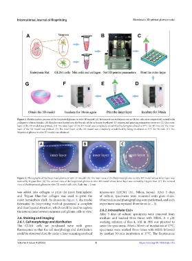
Figure 2. Biofabrication process of the bioprinted glioma in vitro 3D model. (A) Neurons from embryonic rat or GL261 cells were respectively mixed with
collagen to obtain bioinks. (B) Bioinks were loaded into the barrels of the in-house developed 3D printer, and printing parameters were set. (C) The outer
layer of the 3D model was printed. (D) The outer layer of the 3D model was completely crosslinked by being incubated at 37°C for 30 min. (E) The inner
layer of the 3D model was printed. (F) The inner layer of the 3D model was completely crosslinked by being incubated at 37°C for 30 min. (G) The
bioprinted glioma in vitro 3D model was obtained.
Figure 3. Photographs of the bioprinted glioma in vitro 3D model. (A) The main view of the bioprinted glioma in vitro 3D model whose inner layer was
stained by Trypan Blue. (B) The vertical view of the bioprinted glioma in vitro 3D model whose inner layer was stained by Trypan Blue. (C) The vertical
view of the bioprinted glioma in vitro 3D model with cells. Scale bar = 2 mm.
was added into collagen to print the inner hemisphere, microscope (LSCM) (A1, Nikon, Japan). After 5 days
and Trypan Blue-free collagen was used to print the of culture, specimens were mounted onto glass slides.
outer hemisphere shell. As shown in Figure 3, the model Observation and photographing were performed, and each
fabricated by bioprinting method possessed a complete experiment was repeated three times (n = 3).
and clear layered structure, which could be used to explore
the interactions between neurons and glioma cells in vitro. 2.6.2. Intracellular Ca2+
After 5 days of culture, specimens were removed from
2.6. Staining and imaging medium and washed three times with HBSS. A 4 µM
2.6.1. Cell morphology and distribution working solution of fluo-4, AM in PBS was pipetted to
The GL261 cells we purchased were with green cover the specimens. After a 30 min of incubation at 37°C,
fluorescence so that the cell morphology and distribution specimens were washed three times with HBSS followed
could be observed directly under a laser scanning confocal by another 30-min incubation at 37°C. The fluorescence
Volume 9 Issue 4 (2023) 5 https://doi.org/10.18063/ijb.715