
Page 292 - IJB-9-4
P. 292
International Journal of Bioprinting 3D printing of continuous fiber reinforced PLA/PGA composites
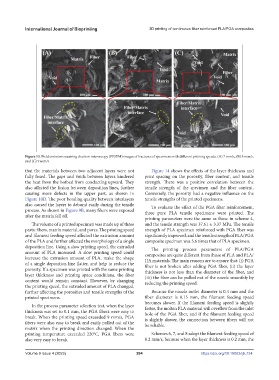
Figure 13. Field emission scanning electron microscopy (FESEM) images of fractures of specimens with different printing speeds. (A) 7 mm/s, (B) 8 mm/s,
and (C) 9 mm/s.
that the materials between two adjacent layers were not Figure 14 shows the effects of the layer thickness and
fully fused. The gaps and voids between layers hindered print spacing on the porosity, fiber content, and tensile
the heat from the hotbed from conducting upward. They strength. There was a positive correlation between the
also affected the fusion between deposition lines, further tensile strength of the specimen and the fiber content.
causing more defects in the upper part, as shown in Conversely, the porosity had a negative influence on the
Figure 10D. The poor bonding quality between interlayers tensile strengths of the printed specimens.
also caused the layers to debond easily during the tensile To evaluate the effect of the PGA fiber reinforcement,
process. As shown in Figure 9B, many fibers were exposed three pure PLA tensile specimens were printed. The
after the matrix fell off.
printing parameters were the same as those in scheme 4,
The volume of a printed specimen was made up of three and the tensile strength was 37.61 ± 3.37 MPa. The tensile
parts: fibers, matrix material, and pores. The printing speed strength of PLA specimen reinforced with PGA fiber was
and filament feeding speed affected the extrusion amount significantly improved, and the tensile strength of PLA/PGA
of the PLA and further affected the morphology of a single composite specimen was 5.6 times that of PLA specimen.
deposition line. Using a slow printing speed, the extruded The printing process parameters of PLA/PGA
amount of PLA increased. A slow printing speed could composites are quite different from those of PLA and PLA/
increase the extrusion amount of PLA, make the shape HA materials. The main reasons are to ensure that: (i) PGA
of a single deposition line flatter, and help to reduce the fiber is not broken after adding PGA fiber, (ii) the layer
porosity. If a specimen was printed with the same printing thickness is not less than the diameter of the fiber, and
layer thickness and printing space conditions, the fiber (iii) the fiber can be pulled out of the nozzle smoothly by
content would remain constant. However, by changing reducing the printing speed.
the printing speed, the extruded amount of PLA changed,
further affecting the porosities and tensile strengths of the Because the nozzle outlet diameter is 0.4 mm and the
printed specimens. fiber diameter is 0.15 mm, the filament feeding speed
becomes slower. If the filament feeding speed is slightly
In the process parameter selection test, when the layer
thickness was set to 0.1 mm, the PGA fibers were easy to faster, the molten PLA material will overflow from the inlet
hole of the PGA fiber, and if the filament feeding speed
break. When the printing speed exceeded 9 mm/s, PGA is slightly slower, the connection between fibers will not
fibers were also easy to break and easily pulled out of the be reliable.
matrix when the printing direction changed. When the
printing temperature exceeded 220°C, PGA fibers were Schemes 6, 7, and 8 adopt the filament feeding speed of
also very easy to break. 0.2 mm/s, because when the layer thickness is 0.2 mm, the
Volume 9 Issue 4 (2023) 284 https://doi.org/10.18063/ijb.734