
Page 401 - IJB-9-4
P. 401
International Journal of Bioprinting Impingement shear stress during microvalve-based bioprinting
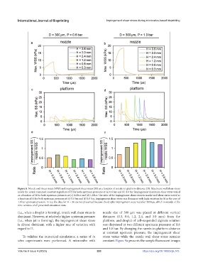
Figure 8. Nozzle wall shear stress (WSS) and impingement shear stress (SS) as a function of nozzle-to-platform distance (H). Maximum wall shear stress
inside the nozzle remained constant regardless of H for both upstream pressures at (a) 0.6 bar and (b) 1.0 bar. Impingement maximum shear stress varied
as a function of H for both upstream pressures at (c) 0.6 bar and (d) 1.0 bar. The ratio of the impingement shear stress to nozzle wall shear stress varied as
a function of H for both upstream pressures at (e) 0.6 bar and (f) 1.0 bar. Impingement shear stress was dominant with high variation for H in the case of
1.0 bar upstream pressure. In (c), the data for H = 36 are not presented because the droplet impingement occurred after 2000 µs, which is outside of the
time window of all presented simulation data.
(i.e., when a droplet is forming), nozzle wall shear stress is nozzle size of 300 µm was placed at different vertical
dominant. However, at relatively higher upstream pressure distances (0.3, 0.6, 1.2, 2.4, and 3.0 mm) from the
(i.e., when jet is forming), the impingement shear stress platform, and droplet of cell-suspended alginate solution
is almost dominant with a higher rate of variation with was dispensed at two different upstream pressures of 0.6
regard to H. and 1.0 bar. By changing the nozzle-to-platform distance
at constant upstream pressure, the impingement shear
To validate the numerical simulations, a series of in stress varies while the nozzle wall shear stress remains
vitro experiments were performed. A microvalve with constant. Figure 9a presents the sample fluorescent images
Volume 9 Issue 4 (2023) 393 https://doi.org/10.18063/ijb.743