
Page 383 - IJB-9-5
P. 383
International Journal of Bioprinting Vascularized bone regeneration
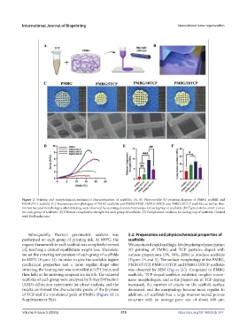
Figure 2. Printing and morphological–mechanical characterization of scaffolds. (A, B) Photocurable 3D printing diagram of PMBG scaffold and
PMBG/TCP scaffold. (C) Macroscopic morphologies of PMBG scaffolds and PMBG/5TCP, PMBG/10TCP, and PMBG/20TCP scaffolds, as well as their
microstructural morphologies after sintering, were observed by scanning electron microscopy for each group of scaffolds. (D) Typical stress–strain curves
for each group of scaffolds. (E) Ultimate compressive strength for each group of scaffolds. (F) Compression modulus for each group of scaffolds. Created
with BioRender.com.
Subsequently, thermal gravimetric analysis was 3.2. Preparation and physicochemical properties of
performed on each group of printing ink. At 800°C, the scaffolds
organic framework in each scaffold was completely burned We conducted rapid and high-fidelity photopolymerization
off, reaching a critical equilibrium weight loss. Therefore, 3D printing of PMBG and TCP particles doped with
we set the sintering temperature of each group of scaffolds various proportions (5%, 10%, 20%) to produce scaffolds
to 850°C (Figure 1I). In order to give the scaffolds higher (Figure 2A and B). The surface morphology of the PMBG,
mechanical properties and a more regular shape after PMBG/5TCP, PMBG/10TCP, and PMBG/20TCP scaffolds
sintering, the heating rate was controlled at 0.5°C/min, and was observed by SEM (Figure 2C). Compared to PMBG
then held at the sintering temperature for 6 h. The sintered scaffolds, TCP-doped scaffolds exhibited rougher micro-
scaffolds of each group were analyzed by X-Ray Diffraction nano morphologies, and as the proportion of TCP doping
(XRD) diffraction experiment for phase analysis, and the increased, the number of cracks on the scaffold surface
results confirmed the characteristic peaks of the β-phase decreased, and the morphology became more regular. In
of TCP and the unoriented peak of PMBG (Figure S1 in addition, all scaffolds had a large interconnected porous
Supplementary File). structure with an average pore size of about 400 µm.
Volume 9 Issue 5 (2023) 375 https://doi.org/10.18063/ijb.767