
Page 43 - MSAM-1-1
P. 43
Materials Science in Additive Manufacturing Crack-free AA7075 with Zr modification via LPBF
A E B F
C G D H
I
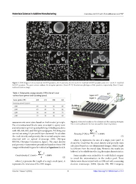
Figure 1. SEM images of (A) as-received AA7075 powders, (B) Zr particles, (C) 0.3 w.t.% Zr-modified AA7075 powders, and (D) 1 w.t.% Zr-modified
AA7075 powders. The green arrows indicate the irregular particles. (Insets E–H) Detailed morphologies of the powders, respectively, (Inset I) back-
scattered electron image.
Table 2. Volumetric energy density (VED, J/mm ) over
3
various laser power and scanning speed.
Laser power (W) 250 275 300 325
Scanning speed (mm/s)
1000 69 76 83 90
1100 63 69 76 82
1200 58 64 69 75
1300 53 58 64 69
measurements were taken based on Archimedes’ principle. Figure 2. Fabricated samples on the substrate and the scanning strategies.
The microstructural blocks were mounted in epoxy resin The xz and xy planes in the inset are used for observing defects.
and subjected to grinding and polishing. Grinding was done
with 400, 600, 800, and 1000 grit sandpapers. Polishing was ∑ i A
carried out using 2.5 μm and 0.5 μm diamond. To calculate Porosity P n= 1 i × 100%
, (%) =
the crack density and porosity, the mounted samples were A (3)
observed with an optical microscope (OM; Olympus where A represents the area of a single pore (μm ). It
2
i
BX53M, Olympus Corporation, Japan). The crack density should be noted that the crack density and porosity were
and porosity measurement procedures based on these OM calculated based on two-dimensional images, which might
images without etching are formulated as Equations 2 and 3.
be different from the overall data. However, the results are
∑ i l i believed to be reliable in reflecting the major characteristics.
Crack density C ) = n =1 ×100% Some samples were etched for 8 s with Keller’s reagent
, (/um
A (2) to reveal the microstructure in the molten pool. These
where l represents the length of a single crack (μm), A blocks were characterized with an OM and with a scanning
i
represents the total area of the OM images. electron microscope (SEM; Quanta 250, FEI Company,
Volume 1 Issue 1 (2022) 4 https://doi.org/10.18063/msam.v1i1.4