
Page 80 - MSAM-1-1
P. 80
Materials Science in Additive Manufacturing A ML model for AM PSP of Ti64
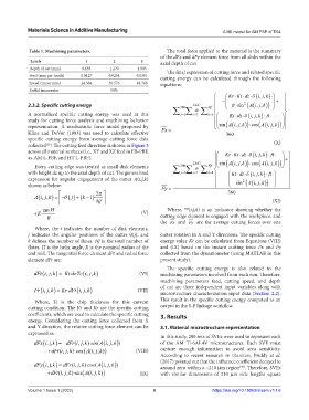
Table 1. Machining parameters. The total force applied to the material is the summary
of the dFx and dFy element force from all disks within the
Levels 1 2 3 axial depth of cut.
Depth of cut (mm) 0.635 1.270 1.905 The final expression of cutting force and related specific
Feed (mm per tooth) 0.0127 0.0254 0.0381 cutting energy can be calculated through the following
Speed (m per min) 24.384 36.576 48.768 equations:
Radial immersion 50%
Kr Kt dz ij k,,
2
2.3.2. Specific cutting energy 360 DoC Nf ft sin Ai jk ,
,
dz
A normalized specific cutting energy was used in this k1 Kt dz ij k ,, ft
j1
i1
study for cutting force analysis and machining behavior
representation. A mechanistic force model proposed by Fx sin Ai jk, , Ai jkcos ,,
Kline and DeVor (1983) was used to calculate effective 360
specific cutting energy from average cutting force data (X)
collected . The cutting feed direction is shown in Figure 3
[39]
across all material surfaces (i.e., XY and XZ feed in EB-PBF, Kr Kt dz ft
as-AM L-PBF, and HT L-PBF). ij k,,
, ,jk
DoC sin Ai jk Ai
cos
, ,
Every cutting edge was treated as small disk elements Nf
360
dz
with height dz up to the axial depth of cut. The generalized j1 i1 k1 Kt dz ft
,,ij k
expression for angular engagement of the cutter A(i,j,k) 2
shown as below: Fy sin Ai , ,jk
Ai jk,, k 1 · 2 360
j
Nf (XI)
Where, (i,j,k) is an indicator showing whether the
Z· tan H (V) cutting edge element is engaged with the workpiece, and
R
the Fx and Fy are the average cutting forces over one
Where, the i indicates the number of disk elements,
j indicates the angular positions of the cutter θ(j), and cutter rotation in X and Y directions. The specific cutting
k defines the number of flutes. Nf is the total number of energy value Kt can be calculated from Equations (VIII)
flutes. H is the helix angle, R is the nominal radius of the and (IX) based on the instant cutting force Fx and Fy
end mill. The tangential force element dFt and radial force collected from the dynamometer (using MATLAB in this
element dFr are: present study).
The specific cutting energy is also related to the
)
dFt ( ,,i j k = · ·Kt dz Tc ( ,,i j k ) (VI) machining parameters involved from each run. Therefore,
machining parameters feed, cutting speed, and depth
Fr ij k,, KrdFt ij k· , , (VII) of cut are three independent input variables along with
microstructure characterization input data (Section 2.2).
Where, Tc is the chip thickness for this current This result in the specific cutting energy computed as an
cutting condition. The Kt and Kr are the specific cutting output in the S-P linkage workflow.
coefficients, which are used to calculate the specific cutting 3. Results
energy. Considering the cutting force collected from X
and Y direction, the relative cutting force element can be 3.1. Material microstructure representation
expressed as: In this study, 200 sets of SVEs were used to represent each
dFxi,,j dFr ij ksin Ai jk(, ,)· ( ,, ) of the AM Ti-6Al-4V microstructures. Each SVE must
k
dFti jk(, , )·cos Ai jk(, , )) (VIII) capture enough information to avoid area sensitivity.
According to recent research in titanium, Priddy et al.
dFyi,,j dFr ij kcos Ai jk(, ,)· ( ,, ) (2017) pointed out that the influence coefficient decayed to
k
around zero within a ~210 µm region . Therefore, SVEs
[40]
dFti jk(, , )·sin Ai jk(, ,) (IX) with similar dimensions of 210 µm side lengths square
Volume 1 Issue 1 (2022) 8 https://doi.org/10.18063/msam.v1i1.6