
Page 50 - MSAM-1-2
P. 50
Materials Science in Additive Manufacturing Process study of DED steel matrix composites
Table 3. L9 Taguchi array with estimated powder flow rate and energy density
Taguchi Run Laser power Scanning speed Hopper speed Estimated powder Energy density
Number Order (W) (mm/min) (rpm) rate (g/min) (J/mm )
2
1 1 1000 200 200 5.44 100.0
2 2 1000 400 300 7.85 50.0
3 3 1000 600 400 9.95 33.3
4 8 1200 200 300 7.85 120.0
5 9 1200 400 400 9.95 60.0
6 7 1200 600 200 5.44 40.0
7 6 1400 200 400 9.95 140.0
8 4 1400 400 200 5.44 70.0
9 5 1400 600 300 7.85 46.7
2.4. Density measurements
The method of hydrostatic weighing was used to measure
the bulk density of the polished samples based on
Archimedes’ Principle. The XS204 balance machine with
density kit (Mettler Toledo, Switzerland) was used to
perform the density tests.
The actual TiB content of the DED samples was
2
calculated using the rule of mixture:
1 1
−
= f ρ ρ S (2)
1 − 1
ρ ρ
T S
Figure 2. Scanning path used in directed energy deposition.
Where f is the weight fraction of TiB , P and P
2
T
s
are the density of 316L stainless steel (8.00 g/cm ) and A B
3
TiB (4.52 g/cm ), respectively. The calculated TiB weight
3
2
2
fraction assumes that the DED samples have no porosity.
2.5. Microhardness
The Vickers hardness of the polished samples was measured
using FM-300e hardness tester (Micro Measurement Pte
Ltd, Singapore) at a load of 300 g for 15 s, according to ISO
6507-1:2018. Six evenly spaced indentations were made on
both the top and side surfaces.
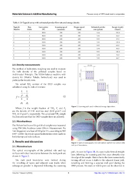
3. Results and discussion Figure 3. Optical micrographs: (A) side surface and (B) top surface with
3.1. Microstructure melt pool boundaries.
The optical micrographs of the polished side and top path. As seen in Figure 3B, the scan tracks formed straight
surfaces with clear boundaries between the melt pools are lines following the scanning path but stops abruptly near
shown in Figure 3.
the edge of the sample. This is due to the laser momentarily
The melt pool boundaries were formed during turning off and on as it shifts to the adjacent linear path,
the remelting of layers and adjacent scan tracks when remelting and forming a separate melt pool during the
subsequent powder is deposited following the scanning DED process. No crack or visible pore can be observed in
Volume 1 Issue 2 (2022) 4 http://doi.org/10.18063/msam.v1i2.13