
Page 117 - MSAM-2-3
P. 117
Materials Science in Additive Manufacturing SLA 3D printed triaxial nozzle
A B
C D
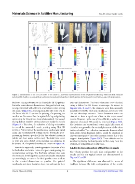
Figure 2. An illustration of the 3D CAD model of the nozzle (A), and visual representations of the 3D-printed nozzle using white and clear FormLabs
materials (B). Backflow assessment (top) and normal operation (bottom) fluid velocity profiles for the nozzle (C) and typical nozzle (D) are presented.
PreForm slicing software for the FormLabs 3B 3D printer. external dimensions. The inner diameters were checked
Since the inner channel diameter was designed to be 1 mm, using a Nikon SMZ25 Stereo Microscope. As shown in
we experimented with different orientations when slicing Figures S3A, B, and D, the channels were dimensionally
the nozzle (Figure S1). Subsequently, the files were sent to accurate in both the inlet and outlet areas, consistent with
the FormLabs 3B 3D printer for printing. On printing the the 1% shrinkage estimate. These deviations were not
nozzles, we discovered that the optimal slicing and printing deemed to have a significant effect on the experimental
orientation for these inner channels is vertical. Horizontal results. However, in the case of the cell inlet, a reduction in
slicing did not result in printed channels inside the nozzle diameter of around 30% could be observed (Figure S3B).
(Figure S1). Therefore, the selection of slicing orientation The deviation can be attributed to the angled placement of
is crucial for successful nozzle printing using SLA 3D the inlet, as opposed to the vertical placement of the other
printing. Post-printing, the nozzles were washed and cured inlets and outlet. This reduction in diameter does not affect
using the recommended settings on the FormLabs post- printability. Small localized defects could be observed in
processing devices, specifically for the selected materials the outermost part of the outlet in some nozzles due to the
(white and clear resins in this case). The total time taken support touchpoints (Figure S3C). These defects can be
to print and cure a batch of five nozzles was estimated to avoided by placing the touchpoints further away from the
be around 7h. The printed nozzles are shown in Figure 2B. channel, or using smaller touchpoints.
FormLabs reported a shrinkage rate in the order of 1% 3.2. Finite element analysis of fluid flow in nozzle
for both clear and white resins after post-curing using the
recommended settings. The PreForm software also took The velocity profiles for each inlet configuration in the
the estimated shrinkage into account and scales structures nozzle and for the typical nozzle are demonstrated in
up accordingly to ensure the final product was as close Figures 2C and D.
to the nominal dimensions as possible. Our printed No significant difference was observed in terms of
nozzles did not show deviation from that estimate in their backflow between the inlet configurations of the nozzle,
Volume 2 Issue 3 (2023) 6 https://doi.org/10.36922/msam.1786