
Page 134 - MSAM-2-3
P. 134
Materials Science in Additive Manufacturing Powder alteration caused by L-PBF process
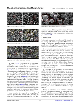
Figure 23. Morphologies of new powder. Figure 26. Heat-affected powder trapped in sieve device.
shattered particles, deformed particles, elongated particles,
aggregates, and particles with molten specks. This powder
alteration is attributed to the effect of melting and sintering
process [11,16,23,35,36,42,43] .
4. Conclusion
In this study, we examined the evolution of PSD throughout
the printing cycle and recycling of the L-PBF process, as
Figure 24. Morphologies of powder reused 12 times. well as the influence of printed component geometry on
powder size and morphology. The conclusions from the
different experiments are summarized as follows:
In experiment 1, we examined how powder was spread
on the bed. The results showed that the powder is not
uniformly spread over the build plate. Therefore, the PSD
changed more along horizontal lines than along vertical
lines, due to the recoater effect and powder flowability.
When moving horizontally toward the collector, the
diameter D-values D90, D50, and D10 progressively
Figure 25. Powder confined within 3-mm-cell lattice. increased. For example, the D50 increased by 9.8%, 10.8%,
9.6%, and 14.6% for the four different lines. However,
As shown in Figure 23, the morphology of new powder moving from the top to the bottom of the powder bed
is globally spherical with the presence of satellites and through the vertical columns j = 1, 2, 3, and 4, the diameters
aggregates particles (indicated with red circles), which are D-values mildly reduced.
formed during the powder production process. However,
Figure 24 shows that the powder recycled 12 times exhibits In experiment 2A, we printed a filled cylinder in the
the presence of satellites, deformed particles (indicated with middle of the build plate. The printing process produced
orange circles), “clip-clap” (indicated with blue circles), spatters that were deposited in the inferior region of the
and elongated particles (indicated with yellow circles). powder bed due to the effect of gas flow, but their influence
Furthermore, as shown in Figure 25, the powder inside on PSD along the vertical axis (Y-axis) was negligible.
the 3-mm-cell lattice shows a high shape degradation. The Nevertheless, the powder samples obtained along the
particles are deformed and exhibit a relevant amount of horizontal line (X-axis) showed an increase in PSD in the
aggregates, elongated particles, broken particles (indicated direction of the recoater, as measured in experiment 1. In
with green circles), and shattered particles (indicated with experiment 2B, we examined the influence of part distance
white circles). Finally, Figure 26 shows spatters and heat- spacing on PSD. We conclude that decreasing the spacing
affected particles that are trapped within the 80-µm-mesh between parts narrows and shifts the PSD toward larger
sieve device. The particles exhibit a wide scale of aggregate particles.
particles in addition to the presence of spherical larger Finally, in experiment 3, we examined a printing
particles “super ball” (indicated by purple circles). situation with significant potential for powder alteration.
Many researches have reported the morphology of We printed lattice structures of different cell sizes and
degraded particles after reusing cycles, especially the analyzed the PSD and the morphology of the powder
presence of defects such as broken particles, “clip-clap,” trapped within the lattices. The PSD was quite different for
Volume 2 Issue 3 (2023) 11 https://doi.org/10.36922/msam.1781