
Page 68 - MSAM-2-4
P. 68
Materials Science in Additive Manufacturing Base shape generation for HAM
skeleton from a voxel model, we applied to this study the skeleton is generated by connecting the voxel centers,
a parallel 3D medial surface/axis thinning algorithm it does not have very smooth surface and the accuracy
proposed in literature , which is an efficient 3D parallel could be influenced by the voxel resolution. Therefore,
[45]
thinning algorithm for extracting both the medial the initial skeleton cannot be directly used for generating
surfaces and the medial axes of a 3D object (given as a base shape as post-processing is required. In this research,
3D binary image). Based on this method, the voxel model slightly curved skeleton branches or small bent poly
was processed by the adopted algorithm; the initial branches were simplified and replaced by straight line
skeleton obtained is shown in Figure 4C. However, since segments to facilitate the following base shape generation.
The simplified skeleton of the tree structure is shown in
A B
Figure 4D.
3.2.2. Step 2: Original subpart generation and branch
set optimization
The base shape was generated by decomposing the skeleton
and then sweeping some simple cross-sections like circles,
along the selected branch set. Moreover, the corresponding
volume of each branch was used to optimize the candidates;
therefore, the model needs to be decomposed as well. The
Figure 2. Solid model representation by voxel layers. (A) The selected voxel
distribution for a solid model in one layer; (B) 3D voxel configuration for decomposition of original subparts, as shown in Figure 5,
the solid model. was based on the skeleton and CAD model, and the end
A B C D
E F G H
Figure 3. Voxelization by ray intersection for a model with different resolution. (A) Voxel meshing based on a bounding box; (B) center points generation;
(C) internal point identification; (D) assembly of identified pixels; and (E-H) voxelization with a higher resolution.
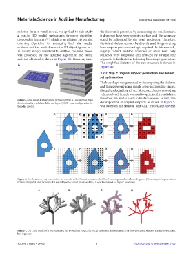
A B C D
Figure 4. (A) CAD model of a tree structure; (B) a voxelized result; (C) initial generated skeleton; and (D) a post-processed skeleton replaced by straight
line segments.
Volume 2 Issue 4 (2023) 5 https://doi.org/10.36922/msam.2103