
Page 67 - MSAM-2-4
P. 67
Materials Science in Additive Manufacturing Base shape generation for HAM
The hybrid processing can start from zero or an existing (ii) Generate the optimal branch set, which has the largest
volume as discussed above. Processing from existing volume of the corresponding volume of the original
volume can help save material and processing time. The CAD model. Decompose the skeleton into a set of
non-additive manufacturing process is able to build branches and the CAD model into original subparts
the physical component of a CAD model from existing using the intersection points on the skeleton. If
relatively simple shapes, which could be subsections necessary, remove a set of non-important sub-branches
of the physical model, called base shape in this paper. and extract the key branches, but all branches are kept
However, how to determine an optimal base shape to in this research. The optimal branch set is a group of
save printing time, avoid manufacturing constraints, and branches which are adjacent, and coplanar, as well as,
ensure component quality is an open question for the with the largest volume of the corresponding subparts
process planning and has rarely been investigated. To of the CAD model.
address it, this paper proposes a model skeleton-based (iii) Generate alternative base shapes based on a set of pre-
decomposition method to generate alternative base defined 2D cross-section profiles (primary shapes,
shapes. A set of generic evaluation criteria are defined e.g., circles and polygons) sweeping along the optimal
for alternative evaluation. In this paper, we also present branch set to generate 3D volumes. Based on the various
the application of the proposed method, together with sizes of selected 2D cross-section profiles, generate
cold spraying coupled to computer numerical control numerous base shapes, which are known as “candidate
machining (as post-processing in a sequential way base shapes.” Search the “optimal candidate base shape”
after printing), for the determination of base shape in a using evolutionary computational methods. The material
hybrid AM process. Certainly, the proposed method can use rate is used to obtain the optimal base shape.
be adopted for other hybrid AM processes after specific
manufacturing constraints are taken into consideration. 3.2. Method implementation
The implementation details of the above-mentioned three
3.1. Method overview
steps entailed in the proposed global method are given below:
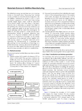
The proposed method includes three main steps, as shown
in Figure 1: 3.2.1. Step 1: Voxelization and skeleton generation
(i) Voxelize a given CAD model in the format of STL to For voxelization, the method proposed in the literature
[44]
obtain a voxel model. Then, generate a skeleton, the was adopted. This method allows efficient conversion of
medial axis, from the voxel model to represent the polygonal solid models into voxel format with a maximum
general topological relationship of the original CAD resolution of 1000 (1 billion voxels) in <2 min. In this
model. The skeleton allows defining the “material research, the voxelization algorithm was used to convert a
deposition directions,” which is used when searching solid model obtained from a CAD system in STL format.
“decomposition” of basic volumes into “subparts.” The voxel size is determined by dividing the maximum
dimension of the bounding box of the STL model with a
desired resolution. The voxelization process essentially
passes rays along the X-axis in a preset order (increments
along Y axis first, then along Z axis) and finds their
intersections with the facets. The number of intersections
for any ray is always even if the STL file is free of errors
and the rays completely extend beyond the model on
both sides, as shown in Figure 2. The voxelization process
essentially passes rays along the X-axis in a preset order
(increments along the Y-axis first, then along the Z-axis)
to find their intersections with the facets. The process was
carried out in a layer-by-layer fashion from the minimum
to the maximum Z coordinate of the model, as depicted in
Figure 3.
Figure 4 illustrates the examples of CAD models
with complex tree shape structure. The tree structure
was modeled using a parametric CAD tool called Rhino,
a commercial parametric CAD software based on the
Figure 1. The proposed workflow of base shape generation. NURBS mathematical model. To obtain a topology
Volume 2 Issue 4 (2023) 4 https://doi.org/10.36922/msam.2103