
Page 93 - MSAM-2-4
P. 93
Materials Science in Additive Manufacturing 3D-printed composite auxetic structures
A B C thermoplastic polymer called CFC PA and continuous
fiber-reinforced composite into the nozzle. As shown in
Figure 4, the left nozzle is used for fabricating the plastic
external shell (Figure 4B) and the right nozzle is used to
extrude continuous fiber composites (Figure 4D). The
reinforcing fiber is a 1.5K composite carbon fiber with
a diameter of 0.36 mm and a tensile strength of 2130 ±
230 MPa. Smooth PA, CFC PA, and composite carbon
fiber were obtained from Anisoprint . The mechanical
[32]
properties of the printing materials are listed in Table 1.
The printing temperature of both nozzles is 240°C, and the
building plate temperature is 60°C.
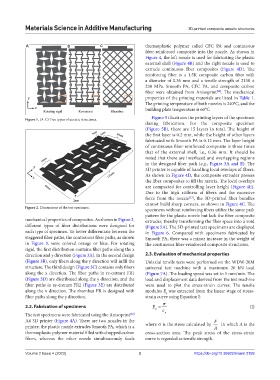
Figure 1. (A-C) Tree types of auxetic structures. Figure 5 illustrates the printing layers of the specimen
during fabrication. For the composite specimen
(Figure 5B), there are 15 layers in total. The height of
the first layer is 0.2 mm, while the height of other layers
fabricated with Smooth PA is 0.12 mm. The layer height
of continuous fiber-reinforced composite is three times
that of the external shell, i.e., 0.36 mm. It should be
noted that there are interlaced and overlapping regions
in the designed fiber path (e.g., Figure 3A and E). The
3D printer is capable of handling local overlaps of fibers.
As shown in Figure 4D, the composite extruder presses
the fiber composites to fill the matrix. The local overlaps
are compacted for controlling layer height (Figure 4E).
Due to the high stiffness of fibers and the excessive
force from the nozzle [33] , the 3D-printed fiber bundles
cannot build sharp corners, as shown in Figure 4C. The
Figure 2. Dimensions of the test specimen. specimens without reinforcing fibers utilize the same path
pattern for the plastic nozzle but lack the fiber composite
mechanical properties of composites. As shown in Figure 3, extruder, thereby transforming the fiber space into a void
different types of fiber distributions were designed for (Figure 5A). The 3D-printed test specimens are displayed
each type of specimen. To better differentiate between the in Figure 6. Compared with specimens fabricated by
staggered fiber paths, the continuous fiber paths, as shown Smooth PA, there was a minor increase in the weight of
in Figure 3, were colored orange or blue. For rotating the continuous fiber-reinforced composite structures.
rigid, the first distribution contains fiber paths along the x
direction and y direction (Figure 3A). In the second design 2.3. Evaluation of mechanical properties
(Figure 3B), only fibers along the y direction will infill the Uniaxial tensile tests were performed on the WDW-20M
structure. The third design (Figure 3C) contains only fibers universal test machine with a maximum 20 kN load
along the x direction. The fiber paths in re-entrant FR1 (Figure 7A). The loading speed was set to 5 mm/min. The
(Figure 3D) are distributed along the y direction, and the load and displacement data derived from the test machine
fiber paths in re-entrant FR2 (Figure 3E) are distributed were used to plot the stress-strain curves. The tensile
along the x direction. The rhombus FR is designed with modulus E was extracted from the linear stage of stress-
y
fiber paths along the y direction. strain curve using Equation I:
σ
2.2. Fabrication of specimens E = ε (I)
y
The test specimens were fabricated using the Anisoprint y
[32]
A4 3D printer (Figure 4A). There are two nozzles in the F
printer; the plastic nozzle extrudes Smooth PA, which is a where σ is the stress calculated by A in which A is the
thermoplastic polymer material filled with chopped carbon cross-section area. The peak stress of the stress-strain
fibers, whereas the other nozzle simultaneously feeds curve is regarded as tensile strength.
Volume 2 Issue 4 (2023) 3 https://doi.org/10.36922/msam.2159