
Page 52 - MSAM-3-1
P. 52
Materials Science in Additive Manufacturing Adhesion study for multi-material 3D printing
the glass transition temperature of materials thus better forces within each material, resulting in a clean break on
intermolecule-diffusion between the materials. 30,34 application of stress.
In our investigation of interlaminar adhesion strength, Conversely, samples designed with mechanical
we ensured that sample failures occurred at the interface interlocking features presented a more complex failure
between the two materials, specifically where the cross- behavior. Several of these samples did not fracture along
sectional area of the coupons is the smallest, as delineated the interface plane. Instead, breaks occurred at the smaller
in Figure 4. Through this controlled approach, we were features of the interlocking structure, slightly offset from
able to accurately assess the interface’s failure mechanism the intended plane, as shown in Figure 4B. This deviation
and to determine the interlaminar adhesion strength for was evident from the corrugated appearance of the
each coupon type. fracture surfaces, suggesting that the mechanical interlocks
Our findings revealed that the majority of the samples contributed to a redistribution of stress, thereby altering
exhibited a clean break at the interface, with negligible the failure point. Notably, these failure points typically
remnants of the opposing material adhering to the occurred at the smallest features of the interlocking
fracture surfaces. This phenomenon was predominantly structure, where stress concentration was highest. This
observed in the coupons featuring an unmodified phenomenon can be partly attributed to the rapid cooling of
interface and those with modifications to the top surface’s these small features, printed before the change in material
infill, as shown in Figure 4A and C. Notably, the samples during the dual extrusion process. The larger temperature
with these interfaces displayed a consistent pattern of difference between the deposition zone and the deposited
34
clean separation, indicating a uniform material behavior material at these points likely resulted in weaker bonding.
during failure. A clean break at the interface suggests that Our findings highlight the significant impact of material
the interfacial bond is the weakest link in the coupons change and extruder switching on interfacial adhesion,
since the propagation of a crack will follow the path of particularly in the context of dual extruder 3D printing
least resistance once a crack is initiated under stress. In systems where thermal management during printing plays
other words, this suggests that the interlaminar adhesion a crucial role in determining bond strength.
strength between cPLA and TPU is lower than the tensile These observations provide valuable insights into
strength between these materials. This could be due to the relationship between interface design and failure
the weaker adhesive force compared to the cohesive mechanisms in the cPLA-TPU coupons. The distinct
A B C
D
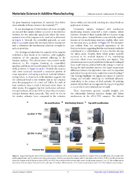
Figure 4. Images showing the typical fracture surfaces on both sides of the tested samples, namely (A) samples with no modification, (B) samples with
interlocking feature, and (C) surface area-enhanced samples. The first row shows the samples with (i) the print order of cPLA TPU, and the second row
shows the samples with (ii) the print order of TPU cPLA. The scale bars at the bottom-right corner of each image represent 1 cm. (D) The red lines in the
schematics show the typical fracture lines for each type of interface. Abbreviations: cPLA: conductive polylactic acid; TPU: Thermoplastic polyurethane.
Volume 3 Issue 1 (2024) 7 https://doi.org/10.36922/msam.2672