
Page 54 - MSAM-3-1
P. 54
Materials Science in Additive Manufacturing Adhesion study for multi-material 3D printing
A B
D
C
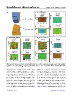
Figure 6. (A) Schematic showing the labels of two scanned fracture surfaces, with (i) representing the fracture surface of the material that is printed last
and (ii) representing the fracture surface of the material that is printed first (B–D) 3D reconstructed height map showing the typical surface morphology
of the fracture surfaces of the interfaces of coupons for no modification, interlocking feature, and top infill modification, respectively. Abbreviations:
cPLA: conductive polylactic acid; TPU: Thermoplastic polyurethane.
adhesion strength and the fracture mode. In particular, we attributed to the design/toolpath that is being used to print
wanted to observe the surface morphology of the material the topmost layer of the first material. It is widely known
situated below the interface (the material that is printed that FFF printing inherently produces parts with grooves
first). In both cases, we observed that the coupons have form between the filaments, explaining why some small
a relatively flat surface with some undulations scattered grooves and valleys are observed on the fractured surface
over the region. For the case of coupons with unmodified of the coupons with unmodified interface. In contrast,
interface, the surface appears to be relatively flat with very for the case of coupons with top infill modification,
few grooves or valleys, as shown in Figure 6B-ii, regardless we intentionally made the gaps between the filament
of the print order. Similar observations can also be made significantly larger, making the filament on the topmost
for the coupons with top infill modifications, but with layer sparsely distributed. This explains why the sparsely
a much wider grooves scattered over the flat fractured distributed filaments appear as the peaks in the height map.
surface. The difference in the surface morphology can be Figure 6B-i and D-i show the surface morphology of the
Volume 3 Issue 1 (2024) 9 https://doi.org/10.36922/msam.2672