
Page 103 - MSAM-4-1
P. 103
Materials Science in Additive Manufacturing Topology optimization of an aluminum bicycle pedal
crank using laser powder bed fusion
values and the designer’s critical opinion, some adaptations a Renishaw AM400 machine (Wotton-under-Edge,
were made to improve the component to improve the United Kingdom) at Hypermetal–Metal AM (Porto,
safety factor to 5. When a safety factor of 5.24 was Portugal). The manufacturing process was prepared using
attained, the component was transferred to new software, Renishaw’s software, which defined the part orientation,
nTopology. The topologically optimized was used to add added necessary supports, and adjusted the laser
interior (Figure 3A) and external lattices (Figure 3B) to parameters for optimal printing.
the component. The lattices were introduced to increase The part was printed using 30-micron layers with a
the complexity of the part in the study since this research stripe strategy and block path. To conserve resources, the
has developed as a hands-on teaching technique. The first bike crank was produced at a 1/5 scale. Once printed,
th
lattice was created in the solid part of the component, the supports were mechanically removed, and the part
and the exterior lattice was used to substitute the central was micro-sandblasted using a Guyson machine (North
depression in the model, intending to decrease mass and Yorkshire, United Kingdom).
improve esthetic appeal.
Despite the scale reduction, all static simulations were
In the TO process, the first step involved the performed with the accurate dimensions of the full-size
introduction of an internal lattice within the solid part crank. The size reduction impacts only manufacturability,
of the component (Figure 3A). This lattice structure was as it could present challenges in ensuring adequate heat
specifically designed to optimize the internal support of dissipation in intricate features, such as lattices, which
the crank while simultaneously reducing the overall mass. could affect print success.
Following this, an external lattice structure was applied to
replace the central depression in the crank (Figure 3B). The 2.2. Powder characterization and chemical
external lattice not only aimed to reduce the weight further composition of AlSi10Mg alloy
but also contributed to the esthetic appeal of the part, This study used powders of an aluminum alloy, AlSi10Mg,
ensuring that both functional and visual considerations from Osprey (Sandvik, Sandviken, Sweden). The chemical
were addressed in the optimization process.
composition is shown in Table 1.
Once the optimized design with the added lattices
Figure 4 shows scanning electron microscopy (SEM)
was finalized, a final static test was conducted within images of AlSi10Mg metal powders supplied by Hypermetal
nTopology, maintaining the same load and displacement (Porto, Portugal), using Osprey powder as the feedstock
constraints. The results of these tests will be discussed in material. The powders were analyzed using SEM/energy-
section 3.2.
The LPBF process was used to manufacture the final Table 1. Chemical composition of AlSi10Mg alloy from
component. The components were produced using Osprey 37
Al Si Mg Fe Ti Mn Cu Ni
Balance 9 – 11 0.2 – 0.4 ≤0.55 ≤0.15 ≤0.45 ≤0.03 ≤0.04
Figure 2. Study setup and the best resulting bike crank (the color scheme
displays the stress distribution on the safety factor defined)
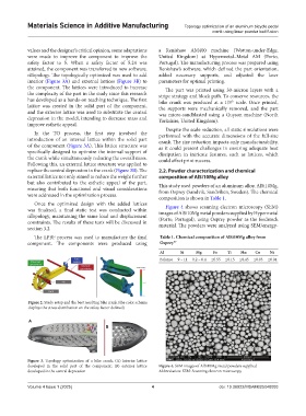
A
B
Figure 3. Topology optimization of a bike crank. (A) Interior lattice
developed in the solid part of the component; (B) exterior lattice Figure 4. SEM images of AlSi10Mg metal powders supplied
developed in the central depression Abbreviation: SEM: Scanning electron microscopy
Volume 4 Issue 1 (2025) 4 doi: 10.36922/MSAM025040003