
Page 102 - MSAM-4-1
P. 102
Materials Science in Additive Manufacturing Topology optimization of an aluminum bicycle pedal
crank using laser powder bed fusion
crucial aspect for applications in industries ranging from applied over 100,000 cycles. In this study, however, the
36
aerospace to consumer products. safety factor was not directly measured but retrieved from
In this context, LPBF is particularly advantageous industry standards and bibliographical sources that align
for materials such as AlSi10Mg, an aluminum alloy with the material properties and typical loading conditions
known for its low density, high thermal conductivity, for similar components. This was used as a design criterion
and good mechanical properties. This makes AlSi10Mg to guide the optimization process.
ideal for creating lightweight, cost-efficient products. The The TO process used the GD module in Autodesk
integration of DfAM and TO enhances LPBF by optimizing Fusion 360 (San Francisco, CA, USA). The following
material distribution within a design space, enabling the procedure was adopted to achieve an optimized design
creation of complex geometries, including internal lattices, suitable for AM:
which are often impractical or impossible to achieve with 1. Initial setup. The optimization began by defining the
traditional manufacturing methods. 1,33,34 geometries to preserve (parts of the component that
This investigation endeavors to optimize a bicycle pedal need to remain intact) and obstacle geometries (areas
crank component for fabrication through AM, explicitly where material could not be added). These parameters
employing LPBF with an aluminum alloy (AlSi10Mg). were essential to ensure the final design adhered to
The objective is to substantiate its production viability and functional and manufacturing constraints
catalyze interest for future integration into the market. 2. Design constraints and load cases. A set of boundary
conditions and load cases was applied, as prescribed
2. Materials and methods by ISO 14781. These constraints included:
10
(a) Pin and fixed geometries: To simulate the
2.1. TO and manufacturing
component’s attachment to the bike and fix its
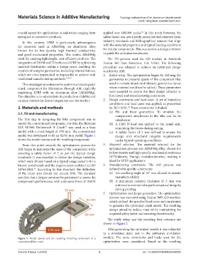
The first step in designing the bike component was to orientation
model the conventional component. For this, the Shimano (b) A 1300 N load was applied to the crank arm,
SLX M7000 Hollowtech II Crank was used as a base simulating the forces during cycling
35
model with a crank length of 170 mm. The conventional (c) A safety factor of 2 was defined to ensure the
model was developed to fit an 82/61 mm pedal. Figure 1 design met structural integrity requirements
shows the model canvas and the resulting component. under typical operating conditions
From this point onward, the optimization process for 3. Material selection. The material selected for the
AM began to minimize the mass of the component while optimization process was AlSi10Mg alloy, chosen for
ensuring a safety factor of 2 as per the typical design its low density and high specific mechanical resistance
standards. It was essential to define the design variables, (UTS/density, Young’s modulus/density), making it
which were chosen based on a typical usage scenario for a ideal for LPBF applications
bicycle pedal crank and the requirements outlined in ISO 4. Manufacturing constraints. The AM process was
14764:2022. According to this standard, the deflection defined with specific constraints:
36
of the crank arm should not exceed 20%. The standard (a) An overhang angle of 45° was allowed to ensure
specifies that a fatigue test must be performed to assess the manufacturability
component’s performance, with a dynamic force of 1300 N (b) A minimum material thickness of 3 mm was
enforced to maintain the part’s structural integrity
during printing
5. Optimization and design generation. The optimization
process was executed using Fusion 360’s GD module,
which utilized the specified load cases and constraints
to generate the optimized crank model. The resulting
design aimed to reduce mass while maintaining the
required safety factor and ensuring functionality.
The study setup and the resulting best outcome are
shown in Figure 2.
After generating the optimized model, it was subjected
to a simulated static test in the software’s simulation
Figure 1. Model canvas and the resulting modeling component of a module. The same constraints and loads used for the
conventional bike crank optimization were considered. Based on the resulting
Volume 4 Issue 1 (2025) 3 doi: 10.36922/MSAM025040003