
Page 74 - MSAM-4-1
P. 74
Materials Science in Additive Manufacturing In situ electromagnetic field manipulation during LMD
A B
C D
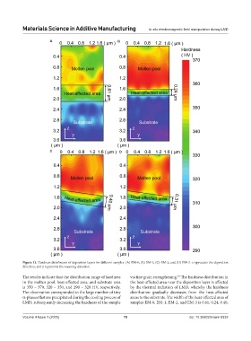
Figure 13. Hardness distribution of deposition layers for different samples: (A) EM-0; (B) EM-1; (C) EM-2; and (D) EM-3. z represents the deposition
direction, and y represents the scanning direction
The results indicate that the distribution range of hardness via fine grain strengthening. The hardness distribution in
40
in the molten pool, heat-affected area, and substrate area the heat-affected area near the deposition layer is affected
is 350 – 370, 320 – 350, and 290 – 320 HV, respectively. by the thermal radiation of LMD, whereby the hardness
The observation corresponded to the large number of tiny distribution gradually decreases from the heat-affected
α-phases that are precipitated during the cooling process of areas to the substrate. The width of the heat-affected area of
LMD, subsequently increasing the hardness of the sample samples EM-0, EM-1, EM-2, and EM-3 is 0.61, 0.24, 0.40,
Volume 4 Issue 1 (2025) 15 doi: 10.36922/msam.8332