
Page 107 - AJWEP-v22i2
P. 107
Assessing drought impacts for adaptive response
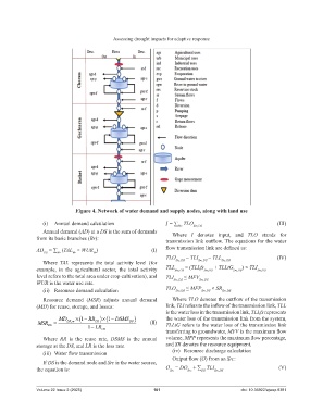
Figure 4. Network of water demand and supply nodes, along with land use
(i) Annual demand calculation I = ∑ TLO (III)
Src Src,DS
Annual demand (AD) at a DS is the sum of demands
Where I denotes input, and TLO stands for
from its basic branches (Br): transmission link outflow. The equations for the water
AD = ∑ (TAL × WUR ) (I) flow transmission link are defined as:
DS Br Br Br
TLO = TLI – TLL (IV)
Where TAL represents the total activity level (for Src,DS Src,DS Src,DS
example, in the agricultural sector, the total activity TLL Src,DS = (TLLfs Src,DS + TLLtG Src,DS ) × TLI Src,DS
level refers to the total area under crop cultivation), and TLI ≤ MFV
WUR is the water use rate. Src,DS Src,DS
(ii) Resource demand calculation TLO Src,DS ≤ MFP Src,DS × SR Src,DS
Resource demand (MSR) adjusts annual demand Where TLO denotes the outflow of the transmission
(MD) for reuse, storage, and losses: link, TLI refers to the inflow of the transmission link, TLL
is the water loss in the transmission link, TLLfs represents
MD ×(1 − RR )×(1 − DSMS ) the water loss of the transmission link from the system,
MSR DS = DS m DS DS (II) TLLtG refers to the water loss of the transmission link
,
1 − LR DS transferring to groundwater, MFV is the maximum flow
Where RR is the reuse rate, DSMS is the annual volume, MFP represents the maximum flow percentage,
storage at the DS, and LR is the loss rate. and SR denotes the resource equipment.
(iii) Water flow transmission (iv) Resource discharge calculation
Output flow (O) from an Src:
If DS is the demand node and Src is the water source,
the equation is: O = DO + ∑ TLI Src,DS (V)
DS
Src
Src
Volume 22 Issue 2 (2025) 101 doi: 10.36922/ajwep.8381