
Page 119 - AN-3-3
P. 119
Advanced Neurology Evaluating plausibility of thalamic model
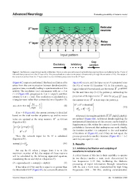
Figure 5. The thalamic computational model architecture. This is an auto-associative neural network where input patterns are duplicated in the 1 layer of
st
REs and then projected onto the 2 layer of Rs. This process leads to a reduction in pattern dimensionality through the extraction of PCs. The output of
nd
the network is derived from the 1 layer, which receives inhibitory projections from the 2 layer.
st
nd
(Figure 6C) steps are performed. The basal oscillation of Rs Figure 6G occurs, and the input vector I is projected onto
p
arises from the communication between dendrodendritic the PCs of vector Oj (Equation VI). In this scenario, the
gap junctions, eventually leading to synchronization of this logical value of O is evaluated, and the vector R is updated
i
j
activity. The oscillation (osc) commences with osc = 0 at for the next time step (t+1) for pattern p, subtracting the
t = 0 (Figure 6D), progresses to 1 at t = steps/2, and then
p
j
returns to 0 at t = steps. This oscillation is calculated as a projection of the input vector I onto the PCs of O from
triangular wave rather than a sinusoidal one (Equation II): the current vector R at time step t for pattern p.
i
2 O O threshold
j
j
.
osc 05 05 . sin t (II)
steps 2 R p R p (VI)
p
I
t1 t O j
If osc = 0 (Figure 6E), the current pattern p is identified
based on the total number of patterns np, and its vector Afterward, the weights and shifts , , R O shift ( ), i shift ( )j
j
i
p
value are updated at the relay neurons R as follows are updated (Figure 6H). Additional details regarding the
(Equation III): mathematical foundations of this process can be found in
p p pnp 1 Supplementary File, within the context of a new Euclidean
probabilistic framework that underpins our work. Finally,
(III) the iteration number t is compared to the total number
p
R I p of iterations nt (Figure 6I), and if they are not equal, the
Then, the network input for Rs O is calculated process proceeds to another iteration (Figure 6J) t = t+1
j
(Equation IV). until they are equal (t = nt).
netinp j() = O j (IV) 3. Results
R p
3.1. Inhibitory facilitation and sculpting of
For any Rs O , where j ranges from 1 to m (the waveforms in reticular cells
j
maximum number of Rs), the output of those neurons
will be calculated by the following sigmoidal equation, A critical feature of REs lies in their capability to operate
considering the osc and shift at t (Equation V): in two distinct modes: a tonic mode characterized by
low frequencies (<15 Hz), facilitating the thalamic
O = sigmoid(osc(t) + netinp(j) + shift(t)) (V) processing of input information through interactions
j
If the value of O for any Rs is equal to or greater than with Rs, and a burst mode characterized by high firing
j
the threshold of 0.97 (Figure 6F), the scenario illustrated in frequencies (100 – 500 Hz), enabling communication
Volume 3 Issue 3 (2024) 7 doi: 10.36922/an.3188