
Page 85 - DP-2-1
P. 85
Design+ Analysis of 3D-printed anisotropic cells
mode of FFF objects under severe compression. This technical drawings to constrain fabrication parameters and
4,7
approach was also adopted by several other studies. 8-21 For predict mechanical behavior without requiring intensive
example, Li and Wang studied the mechanical behavior computational methods.
22
of 3D printing sandwiches against bending load. Many For the first two parts of this study, we established
studies also indicated the effect of process parameters on three infill strategies to be analyzed: raster (with 100%
anisotropic behavior. 4,5,23,24 density), grid, and hexagonal infill. For each one of these
However, there are not many investigations on the infill strategies, we have applied a multivariable analysis
connection between process parameters and the mechanical method, where the experiment design was full (2 for 100%
4
strength of FFF items in a computational environment to density raster and 2 for grid and hexagonal infill) with two
3
support design specifications and technical drawings. levels and no central point. The control factors considered
were raster orientation (α), distance between lines (d),
The complexity of objects and their fabrication
parameters can lead to specifications that are not well- layer thickness (h), and bead width (w) for 100% density
raster. For grid infill, we established the distance between
defined. For instance, in building infill strategies, identical lines (d), layer thickness (h), and bead width (w) as control
geometries can yield objects with vastly different mechanical
properties. This issue highlights a broader problem with factors. On the other hand, hexagon diameter (hex), layer
inadequate design specifications and outdated technical thickness (h), and bead width (w) were selected as control
factors for hexagonal infill.
drawing standards. Addressing this challenge, the primary
objective of this study is to introduce a new approach The main responses of this study were young modulus,
for specifying additive manufacturing objects that take Poisson ratios, maximum internal stress, and maximum
into account their mechanical anisotropy. The study is equivalent stress (based on external dimensions of
organized into four sections: numerical characterization, specimen cross-section). In addition, we identified the
experimental characterization, development of a new contribution of the control factors for a generalized
specification method, and evaluation of the proposed orthotropic compliance matrix. This generalized matrix
method. The central idea is to integrate simplified was developed to create a simplified numerical simulation
anisotropic cells into 3D models and technical drawings that is both computationally efficient and easily integrated
to ensure that the final object aligns with both the into technical specifications.
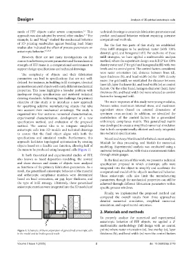
specifications and simulated results. Furthermore, this We utilized Ansys Workbench for finite element analysis,
approach facilitates topological optimization by creating Minitab for data processing, and Matlab for numerical
objects based on a flexible cost function, allowing half of modeling. Experimental analysis was conducted using a
the mass to be produced using hexagonal cells (Figure 1). universal testing machine, with strain measurements taken
In both theoretical and experimental studies of FFF, through strain gauges.
also known as fused deposition modeling, the normal In the final section of this work, we present a technical
and shear stresses and strains of objects were analyzed specification proposal in which anisotropic cells were
as functions of the primary fabrication parameters. As a integrated into the object to simplify and accelerate the
result, the generalized anisotropic behavior of the material computational model of the object’s mechanical behavior.
and orthotropic compliance matrices were determined These anisotropic cells also limit the manufacturing
based on bead orientation, air gap, layer thickness, and parameters, though the mechanical properties can still be
the type of infill strategy. Ultimately, these generalized achieved through different fabrication parameters within
anisotropic matrices were integrated into the 3D model and specific process windows.
Finally, we implemented the proposed method and
compared the overall results from three approaches:
detailed numerical simulation, simplified numerical
simulation, and experimental outcomes.
2. Materials and methods
To properly analyze the numerical and experimental
k
anisotropic behavior of FFF objects, we applied a 2
multivariable methodology (full design with no central
Figure 1. Schematic of the incorporation of generalized anisotropic cells points) where raster orientation (α), line overlap (o), layer
in the model and its final expected result thickness (h), and bead width (w) were the control factors
Volume 2 Issue 1 (2025) 2 doi: 10.36922/dp.3779