
Page 86 - DP-2-1
P. 86
Design+ Analysis of 3D-printed anisotropic cells
for 100% density raster. For grid infill, the analyzed control air gap, and layer height. The general idea of overlap and
factors were air gap (d), layer thickness (h), and bead width hexagon diameter are also represented in this figure. The
(w). On the other hand, we established hexagon diameter hexagon diameter refers to the parameter that controls
(hex), layer thickness (h), and bead width (w) as control the shape of a hexagonal honeycomb. In this case, the
factors of the hexagonal infill design. hexagon is inscribed into a circle with a diameter equal
to the hexagon diameter. This parameter represents a
We defined the equivalent maximum permissible
stress, which is based on the external dimensions of the novel infill parameter, as most slicers calculate the infill
specimen, and the maximum internal permissible stress based on density proportion. It is important to note that
density parameters typically result in variations in infill
as the responses. Furthermore, we analyzed the relative shapes, which, in turn, produce differing anisotropic
Young’s modulus, Poisson’s ratios, strains, normal stresses,
and shear stresses to determine generalized orthotropic effects.
matrices as a function of fabrication parameters. Conversely, filament overlap is a variation of the air gap
that represents a negative air gap. As a result, even if the infill
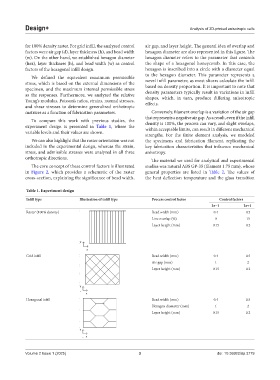
To compare this work with previous studies, the
experiment design is presented in Table 1, where the density is 100%, the process can vary, and slight overlaps,
within acceptable limits, can result in different mechanical
variable levels and their values are shown.
strengths. For the finite element analysis, we modeled
We can also highlight that the raster orientation was not the specimens and fabrication filament, replicating the
included in the experimental design, whereas the strain, key fabrication characteristics that influence mechanical
stress, and admissible stresses were analyzed in all three anisotropy.
orthotropic directions. The material we used for analytical and experimental
The core concept of these control factors is illustrated studies was natural ABS GP-35 (filament 1.75 mm), whose
in Figure 2, which provides a schematic of the raster general properties are listed in Table 2. The values of
cross-section, explaining the significance of bead width, the heat deflection temperature and the glass transition
Table 1. Experiment design
Infill type Illustration of infill type Process control factor Control factors
Lv−1 Lv+1
Raster (100% density) Bead width (mm) 0.4 0.5
Line overlap (%) 0 15
Layer height (mm) 0.15 0.2
Grid infill Bead width (mm) 0.4 0.5
Air gap (mm) 1 2
Layer height (mm) 0.15 0.2
Hexagonal infill Bead width (mm) 0.4 0.5
Hexagon diameter (mm) 1 2
Layer height (mm) 0.15 0.2
Volume 2 Issue 1 (2025) 3 doi: 10.36922/dp.3779