
Page 87 - DP-2-1
P. 87
Design+ Analysis of 3D-printed anisotropic cells
Table 2. General properties of natural ABS 25 A B
Property Standard Value
Tensile strength ASTM D638 36 MPa
Young’s modulus ASTM D638 2.4 GPa
Flexural strength ASTM D790 61 MPa
Flexural modulus ASTM D790 2.3 GPa
C
Elongation at break ASTM D638 4%
HDT 1.82 Mpa ASTM D648 93°C
Abbreviation: HDT: Heat deflection temperature.
temperature (TG) - ASTM D7028 (−83°C) of the material
indicate the thermal workability of the material.
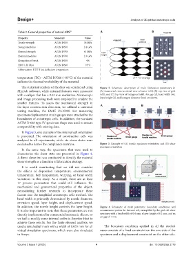
The statistical analysis of the data was conducted using Figure 2. Schematic description of main fabrication parameters in
Minitab software, while external features were measured (A) transversal cross-sectional view of raster infill; (B) top view of grid
with a caliper that has a 0.01 mm resolution. Microscopic infill; and (C) top view of hexagonal infill. Air gap (d), bead width (w),
and image processing tools were employed to analyze the layer height (h), and hexagon diameter (hex) are shown.
smaller features. To assess the mechanical strength in
the layer construction direction, we utilized a universal A B
testing machine, the EMIC DL10000. For measuring
specimen displacement, strain gauges were attached to the
boundaries of anisotropic cells. In addition, the standard
ASTM D 638 type IV specimen shape was used to ensure
comparability with existing data.
In Figure 3, one example of the internal cell orientation
is presented. The orientation of construction cells was
analyzed in all experiments, while six stress states were
evaluated to derive the compliance matrices. Figure 3. Example of (A) tensile specimen orientation and (B) shear
specimen orientation
In the same way, the specimens that were used to
characterize the shear state are presented in Figure 4.
A direct shear test was conducted to identify the material
shear strength as a function of fabrication strategy.
It is worth mentioning that we did not consider
the effects of deposition temperature, environmental
temperature, bed temperature, warping, or bead width
variations in this study. As a result, there are at least
17 process parameters that could still influence the
mechanical and geometrical properties of the object,
necessitating further research to incorporate these
factors into the simplified anisotropic cells method. The
bead width is primarily determined by nozzle diameter,
extrusion speed, layer height, and displacement speed.
In addition, the nozzle height controls the layer height. Figure 4. Schematic of mesh parameter, boundary conditions, and
It is also important to note that these parameters are not measurement probes for the unit cell, exemplified by the grid cell shear
directly implemented in commercial automatic slicers, so specimen with a bead width of 0.4 mm, a layer height of 0.2 mm, and an
we had to modify some internal codes in Repetier Host to air gap of 1 mm.
achieve these results. For the finite element analysis, we
used a tetrahedral mesh with a width of 0.055 mm for all The boundary condition applied in all the studied
virtual simulation specimens, which were also simulated cases consists of a fixed constraint on the one side of the
in Ansys. specimen and a displacement constraint on the other side.
Volume 2 Issue 1 (2025) 4 doi: 10.36922/dp.3779