
Page 22 - ESAM-1-2
P. 22
Engineering Science in
Additive Manufacturing AM-CFRP structures for EMWA properties
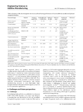
Table 4. Summary of the electromagnetic microwave and load‑bearing performances of recent additively manufactured polymer
composite absorbers
Structural design Material Frequency Bandwidth of RL Minimum Thickness Mechanical References
range (GHz) < −10 dB (GHz) RL (dB) (mm) properties
Bamboo-inspired PEEK/FCIPs 2 – 40 3.2 – 40 −15 3 Compressive yield 69
metastructure magnetic composite stress: 13.27 MPa
Conical structure NFG/Si/Fe O /PF 2 – 18 3.55 – 18 −21.52 21 Compressive yield 70
4
3
composite stress: 5.21 MPa
Electric-loss honeycomb CF/CNT/ABS 2 – 18, 2 – 40 2 – 6.8, 10.4 – 40 < −10 8.67, 13.56, Maximum load: 22
metastructure 14 1.41 kN
Double high-impedance PEEK/ITO/PET 2 – 18 6.73 – 18 −15 4.25 Compressive 75
surface-loaded honeycomb strength: 6.09 MPa;
(DHHC) structure flexural strength:
3.08 MPa
Gradient metastructure FCIPs-PEEK 2 – 18 5.1 – 40 < −15 10 Compressive yield 66
composite stress: 8.46 MPa
Octagon loop with four PEEK/ITO 2 – 30 5.7 – 19.85 < −20 3.97 Compressive yield 81
diagonals metastructure stress: 22.46 MPa
Three-dimensional PLA 1 – 24 3.53 – 24.00 −31.3 15.51 Compressive yield 82
honeycomb metastructure stress: 10.7 MPa
Tree-shaped metastructure ABS/CF/MWCNT 2 – 18, 20 – 40 11.5 – 16 −28.66 10.8 Bending strength: 83
composite 38.8 MPa
Pyramidal array sandwich PLA/CF-reinforced 4 – 18 4 – 18 ≈ −10 13.5 Compressive 68
structure plastics strength: 9.60 MPa
Three-dimensional lossy PLA/CB composite 1 – 40 1.36 – 40 < −20 21.4 Compressive 76
dielectric metastructure strength: 3.75 MPa
Curved-wall honeycomb Chopped CF/glass 2 – 40 2 – 40 −16.5 20 Compressive 87
metastructure fiber strength: 31.3 MPa
Gradient honeycomb TPU/CB composite 2 – 18 2.23 – 18 −15 15 Compressive 86
metastructure strength: 22.89 MPa
Abbreviations: ABS: Acrylonitrile butadiene styrene; CB: Carbon black; CF: Carbon fiber; CNT: Carbon nanotube; FCIP: Flaky carbonyl iron particles;
ITO: Indium tin oxide; NFG: Natural flake graphite; PEEK: Polyether-ether-ketone; PF: Phenol formaldehyde resin; PLA: Polylactic acid; RL: Reflection
loss; TPU: Thermoplastic polyurethane.
honeycomb, lattice, and gradient structures, provide graphene or CNTs tend to aggregate during the extrusion-
excellent mechanical properties and broadband absorption based 3D printing process, resulting in irregular electrical
performance. It revealed an inverse relationship between characteristics and variable microwave absorption.
88
thickness and mechanical efficiency, with optimal designs Overall efficiency may be decreased by isolated
(typically 3 – 15 mm) leveraging cellular geometries and conductive routes caused by this inhomogeneity that
gradual property transitions to minimize trade-offs. These reflect electromagnetic waves instead of absorbing them.
insights underscore the potential of advanced polymer Furthermore, anisotropy is introduced by differences in
materials, architectured metamaterials, and additive fiber alignment and distribution among printed layers,
manufacturing processes to create lightweight, high- which makes it challenging to forecast and regulate
strength absorbers with tunable electromagnetic properties electromagnetic activity. 89-91 Post-processing techniques
for next-generation applications. such as sonication or chemical functionalization may
92
improve dispersion but add complexity to manufacturing.
6. Challenges and future perspectives Future solutions might call for sophisticated material
6.1. Challenges formulations or in situ mixing technologies to guarantee
uniformity during printing.
In developing high-performance additively manufactured
CFRP (AM-CFRP) absorbers, one of the main obstacles The main attenuation mechanism AM-CFRP absorbers
is ensuring the even distribution of CFs and nanofillers use is dielectric losses, which could be inadequate, especially
throughout the polymer matrix. Conductive fillers such as at higher frequencies (such as the millimeter-wave and
Volume 1 Issue 2 (2025) 16 doi: 10.36922/ESAM025160008