
Page 82 - ESAM-1-2
P. 82
Engineering Science in
Additive Manufacturing Porous structure performance improvement
A B C
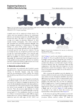
Figure 1. The CAD model of porous materials with different angles between the struts was designed by SolidWorks. The tetrahedral unit cell of different
angles between the struts (A) 99.5°, (B) 109.5°, and (C) 119.5°.
Abbreviation: CAD: Computer-aided design.
rounded corner will be conducted in future studies. The A B
current study also attempted to discuss the compression
behavior and mechanical properties with different angles
between the struts. The effects of rounded corners and
varying strut angles in structures fabricated by SLM
warrant further investigation. This study introduced
and optimized the tetrahedral structure through three
key strategies, including: (1) Optimization of the angles
between the struts of the porous materials, (2) node
chamfering of the porous materials, and (3) introduction
of porosity gradient into the porous materials. During Figure 2. Demonstration of tetrahedral CAD unit cell (A) without and
the mechanical test, the compression direction was fixed (B) with rounded corners
through the z-axis by the specimen. Then, how the angle Abbreviation: CAD: Computer-aided design.
between the struts and structure with rounded corners
affects the capability of energy absorption was discussed. 119.5° (Figure 1) and the unit cell with rounded corners or
Meanwhile, the characteristics and mechanical properties not (Figure 2). Then, the gradient structure was designed
of the gradient porosity materials with these two variables by Magics software; after designing the CAD model, the
(rounded corners and different angles between the struts) unit cells were imported into Magics and filled to create a
are cautiously investigated and discussed. cylinder with a diameter of 18 mm and a height of 36 mm.
To prevent damage from the compression platen during
2. Materials and methods compression, 1 mm thick disks were designed at the top
and bottom to protect the specimens. Then, it was sliced
The experiment was conducted with Ti-6Al-4V powder layer by layer and exported as files that can be read by 3D
manufactured by a domestic metal powder manufacturer
(Chung Yo Materials, Taiwan), using the vacuum printing machines.
induction gas atomization (VIGA) method. The powder When designing the gradient material, adjusting the
size distribution was D10 of 27 m, D50 of 38 m, and D50 thickness of the struts of each unit cell allows for adjustment
of 49 m. of its volume fraction. Through the calculation of porosity,
In this study, specimens were designed by SolidWorks different gradient structures with varying porosities can be
with different angles of the unit cell, and the porosity of designed. In this study, specimens were divided into five
the material was varied by changing the diameters of the gradients: 55%, 60%, 65%, 70%, and 75%. To maintain a
struts. For the tetrahedral structure in the diamond lattice, width-to-height ratio of 1:2 and an average porosity of 65%
we constructed the CAD model along the z-axis, aligning for the middle layer and to be compared with the original
the vertical struts parallel to the compressive loading single porosity of 65%, each porosity was designed to have
direction. Then, the structure angle between the struts a height ratio of 1:1:1.5:1:1 (Figure 3). Each specimen
from its standard 109.5° was adjusted through increasing/ was printed in five copies to ensure the accuracy and
decreasing by 10°. This modification allows us to discuss reproducibility of the experimental data (Figure 4).
the different mechanical behavior under different angles In this study, the naming of the specimens accords with
between the struts. Initially, SolidWorks was used to draw the following rules. “O” signifies original design, indicating
tetrahedral unit cells with angles of 99.5°, 109.5°, and structures without rounded corners. “R” stands for
Volume 1 Issue 2 (2025) 4 doi: 10.36922/ESAM025170009