
Page 86 - ESAM-1-2
P. 86
Engineering Science in
Additive Manufacturing Porous structure performance improvement
leading to fracture at that point, resulting in a lower yield exhibit superior mechanical properties. Specifically, the
strength of the overall structure than expected. yield strength can reach up to a maximum of 26%, and the
compressive strength can reach up to 29%. In addition, they
3.3. Impact of angle between the struts on also demonstrate better energy absorption performance.
mechanical properties Compared to the previous manipulation factor of rounded
Figure 6 illustrates the stress–strain curves for structures corners, structures with larger angles between the struts
with different angles between the struts, whereas Table 4 show greater improvements in strength.
compares the mechanical properties of structures with When a tetrahedron is subjected to vertical compression,
different support angles. According to the experimental the strength along the strut can be divided into a buckling
results, structures with larger angles between the struts
vector B and a bending vector D (Figure 11). Their
relationship with the strut angle θ can be expressed by
Equations V and VI. Furthermore, the buckling vector can
be further divided into normal force N and lateral force
L (Figure 12). Their relationship with the strut angle θ
can be expressed by Equations VII and VIII. Combining
Equations V and VI, they can be rearranged into Equations
IX and X.
B=F‧sin (V)
D=F‧cos (VI)
N=B‧sin (VII)
L=B‧cos (VIII)
N=B‧sin2 (IX)
Figure 9. Side view of specimen fracture shows the fracture on the strut
node with 45° L=B‧cos‧sin (X)
Through the mathematical calculations presented in
A B Table 7, it is evident that as the strut angle θ increases, lateral
force L and buckling vector B increase. The increase in both
the buckling vector and lateral force vectors contributes to
the requirement of greater force and longer compression
deformation. During compression, the material is subjected
to positive compression and squeezed laterally by the
structure, and the structure with a larger angle needs more
deformation to achieve the angle of fracture. Consequently,
when the angle between the struts becomes larger, the
change in angle to achieve fracture during deformation of
the tetrahedral structure also increases. This indicates that
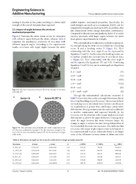
Figure 10. Test specimen cross-sectional area under compression test. structures with larger angles require more deformation to
(A) The area calculated by Equation II for the maximum strength of the
notch; (B) the area calculated by Equation IV for the maximum strength be compressed and fracture, which also leads to the larger
of the notch. value of the difference between strain at failure and stain
Table 6. Maximum strength on the node of a solid strut in single porosity material
Specimen d (mm) ρ (mm) k σ (MPa) σ* (MPa) σ max (MPa)
O_99.5_65 0.71±0.01 0.16±0.01 5.21 143.32 796.22 4148.31
O_109.5_65 0.70±0.04 0.17±0.01 5.06 163.07 905.94 4584.06
O_119.5_65 0.68±0.06 0.16±0.03 5.12 172.10 956.11 4895.28
R_99.5_65 0.65±0.03 1.21±0.08 2.47 147.07 817.06 2018.14
R_109.5_65 0.66±0.05 1.25±0.04 2.45 170.80 948.89 2324.78
R_119.5_65 0.62±0.06 1.24±00.09 2.41 185.10 1028.33 2478.28
Volume 1 Issue 2 (2025) 8 doi: 10.36922/ESAM025170009