
Page 86 - IJAMD-2-3
P. 86
International Journal of AI for
Materials and Design SHM using improved CNT-BP and LSTM-NN
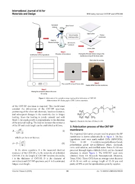
Figure 1. Schematic of the complete setup employed for fabrication of CNT-BP.
Abbreviations: BP: Bucky paper; CNT: Carbon nanotube.
of the CNT-BP specimen is required. This model must
consider the dimensions of the CNT-BP specimen,
positioning of the silver ink electrode, baseline resistance,
and subsequent changes in the resistivity due to fatigue
loading. Since the loading is purely uniaxial and with
Mode I, the crack growth is perpendicular to the direction Figure 2. Chemical structure of Triton X-100
of the uniaxial loading. The relation between the resistance
of the BP and crack length can be established as follows, 3. Fabrication process of the CNT-BP
ρd membrane
R = (I)
( tD − ˆ )a The improved fabrication process used to prepare the BP
which can be re-written as: membranes is shown schematically in Figure 1. The key
ingredients used were multi-walled CNTs (MWCNTs),
ρ d Triton X-100 (t-octylphenoxypolyethoxyethanol,
ˆ a = D − (II)
Rt polyethylene glycol tert-octylphenyl ether), methanol,
nitric acid solution, and distilled water. Triton X-100 was
In the above equations, R is the measured electrical procured through Sigma-Aldrich (USA), and its chemical
resistance of the CNT-BP, ρ is the resistivity of embedded structure is shown Figure 2. The MWCNT used were
CNT-BP, d is the length of CNT-BP between electrodes, obtained from US Research Nanomaterials (Houston,
t is the thickness of CNT-BP, D is the diameter of Texas, USA). These CNTs have an average outer diameter
omnidirectional CNT-BP specimen, and ˆ a is the estimated of 10–30 nm with an average length of 15–30 µm and
fatigue crack length. purity of 90% as per the specifications given by supplier.
Volume 2 Issue 3 (2025) 80 doi: 10.36922/IJAMD025310028