
Page 75 - IJB-1-1
P. 75
Mohammad Vaezi and Shoufeng Yang
moulded at 12–15 MPa and 350℃–375℃. The use of folds with a range of filament and pore sizes through
injection pressures of 11–14 MPa and temperature of conditions presented in Table 1. Infiltration depth was
395℃was previously used in the injection moulding shown to be proportional to the pore size so that the
[4]
of PEEK/HA compounds . Through experimentation, scaffold, with dimensions of 20 × 18 × 3.7 mm, and
the optimal pressure to ensure full infiltration of a filaments sized 910 μm while pores are 1200 μm, was
scaffold at size 10 × 10 × 3 mm without resulting in found to be fully infiltrated by PEEK in both lateral
damage, was determined to be in the region of 0.39 and vertical directions, and HA network retained its
MPa. The optimal pressure used in this study is simi- structure and shape. For similar sized scaffolds that
lar to that used by other researchers in the compres- are 400 µm in filament size but of differing pore sizes
sion moulding of reinforced carbon fibre-PEEK com- (400, 500, 550 and 670 µm), the respective infiltration
posites [30–32] . Luo et al. [30] tested pressures ranging depths are as follows: 1.4, 1.9, 2.4 and 2.9 mm. When
from 0.5 to 2.0 MPa and found that 0.5 MPa is the the infiltration depths—using dynamic loading—are
most suitable pressure for making 3D carbon-fibre compared with the infiltration as seen following static
reinforced PEEK (CFR-PEEK) composites prepared loading, it can be concluded even in scaffolds with
by 3D co-braiding and compression moulding tech- pores of 200 μm that dynamic loading of the molten
niques. Mrse and Piggott [32] employed 0.4 MPa pres- PEEK does not permit sufficient time for flow through
sure for the preparation of AS-4 CFR-PEEK using the scaffold. Infiltration depth was found to be more
lay-up followed by compression moulding process to dependent on the temporal application of pressure
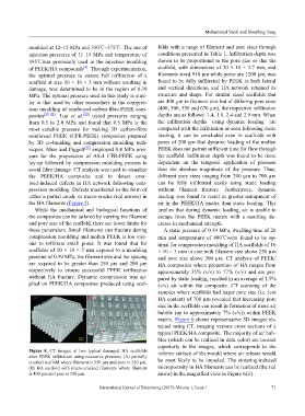
avoid fibre damage. CT analysis was used to visualize than the absolute magnitude of the pressure. Thus,
the PEEK/HA composite and to detect over- different pore sizes ranging from 200 µm to 700 µm
load-induced defects in HA network following com- can be fully infiltrated easily using static loading
pression moulding. Defects manifested in the form of without filament fracture. Furthermore, dynamic
either a partial crush, or micro-cracks (red arrows) in loading was found to result in greater entrapment of
the HA filaments (Figure 5). air in the PEEK/HA matrix than static loading. This
While the mechanical and biological functions of implies that during dynamic loading, air is unable to
the composites can be tailored by varying the filament escape from the PEEK matrix with a resulting de-
and pore size of the scaffold, there are lower limits for crease in mechanical strength.
these parameters. Small filaments can fracture during A static pressure of 0.39 MPa, dwelling time of 20
compression moulding and molten PEEK is too visc- min and temperature of 400℃were found to be op-
ous to infiltrate small pores. It was found that for timal for compression moulding of HA scaffolds of 10
scaffolds of 10 × 10 × 3 mm exposed to a moulding × 10 × 3 mm in size with filament size above 250 µm
pressure of 0.39 MPa, the filament size and the spacing and pore size above 200 µm. CT analysis of PEEK/
are required to be greater than 250 μm and 200 μm HA composites where proportion of HA ranges from
respectively to ensure successful PEEK infiltration approximately 35% (v/v) to 77% (v/v) and are pre-
without HA fracture. Dynamic compression was ap- pared by static loading, resulted in an average of 1.5%
plied on PEEK/HA composites produced using scaf- (v/v) air within the composite. CT scanning of the
samples where scaffolds had larger pore size (i.e. less
HA content) of 700 µm revealed that increasing pore
size in the scaffolds can result in formation of more air
bubble (up to approximately 7% (v/v)) within PEEK
matrix. Figure 6 shows representative 3D images ob-
tained using CT, imaging various cross sections of a
typical PEEK/HA composite. The majority of air bub-
bles (which can be realized in dark color) are located
superiorly in the images, which corresponds to the
Figure 5. CT images of two typical damaged HA scaffolds inferior surface of the mould where air release would
after PEEK infiltration using excessive pressure; (A) partially
crushed scaffold where filament is 250 µm and pore is 250 µm, be most likely to be impeded. The sintering-induced
(B) HA scaffold with micro-cracked filaments where filament microporosity in HA filaments can be realized (the red
is 400 µm and pore is 550 µm. arrow) in the magnified view in Figure 6(E).
International Journal of Bioprinting (2015)–Volume 1, Issue 1 71