
Page 76 - IJB-1-1
P. 76
A novel bioactive PEEK/HA composite with controlled 3D interconnected HA network
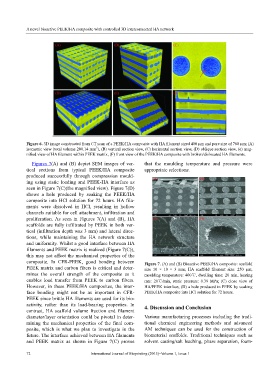
Figure 6. 3D image constructed from CT scan of a PEEK/HA composite with HA filament sized 400 μm and pore size of 700 μm; (A)
3
isometric view (total volume 200.14 mm ), (B) vertical section view, (C) horizontal section view, (D) oblique section view, (e) mag-
nified view of HA filament within PEEK matrix, (F) front view of the PEEK/HA composite with broken/dislocated HA filaments.
Figures 7(A) and (B) depict SEM images of ver- that the moulding temperature and pressure were
tical sections from typical PEEK/HA composite appropriate selections.
produced successfully through compression mould-
ing using static loading and PEEK-HA interface as
seen in Figure 7(C)(the magnified view). Figure 7(D)
shows a hole produced by soaking the PEEK/HA
composite into HCl solution for 72 hours. HA fila-
ments were dissolved in HCl, resulting in hollow
channels suitable for cell attachment, infiltration and
proliferation. As seen in Figures 7(A) and (B), HA
scaffolds are fully infiltrated by PEEK in both ver-
tical (infiltration depth was 3 mm) and lateral direc-
tions, while maintaining the HA network structure
and uniformity. Whilst a good interface between HA
filaments and PEEK matrix is realized (Figure 7(C)),
this may not affect the mechanical properties of the
composite. In CFR-PEEK, good bonding between Figure 7. (A) and (B) Bioactive PEEK/HA composite: scaffold
PEEK matrix and carbon fibers is critical and deter- size 10 × 10 × 3 mm; HA scaffold filament size: 250 µm;
mines the overall strength of the composite as it moulding temperature: 400℃, dwelling time: 20 min, heating
enables load transfer from PEEK to carbon fibers. rate: 20℃/min, static pressure: 0.39 MPa; (C) close view of
However, in these PEEK/HA composites, the inter- HA/PEEK interface; (D) a hole produced in PEEK by soaking
face bonding might not be as important in CFR- PEEK/HA composite into HCl solution for 72 hours.
PEEK since brittle HA filaments are used for its bio-
activity, rather than its load-bearing properties. In 4. Discussion and Conclusion
contrast, HA scaffold volume fraction and filament
diameter/layer orientation could be pivotal in deter- Various manufacturing processes including the tradi-
mining the mechanical properties of the final com- tional chemical engineering methods and advanced
posite, which is what we plan to investigate in the AM techniques can be used for the construction of
future. The interface achieved between HA filaments biomaterial scaffolds. Traditional techniques such as
and PEEK matrix as shown in Figure 7(C) proves solvent casting/salt leaching, phase separation, foam-
72 International Journal of Bioprinting (2015)–Volume 1, Issue 1