
Page 157 - IJB-10-1
P. 157
International Journal of Bioprinting 3D-printed micro-perfused culture device
individual layer is to ensure that the critical dimensions of has other embedded features such as culture chamber
the device were replicated correctly. For instance, channels that holds the 3D fibrous scaffold for cell culture activity.
that delivered the culture medium were designed and printed There are also channels that deliver culture medium and
at a length of 5.9 mm whereas the cells inlet channel was cells to the scaffold, and they are labeled respectively in
designed and printed at a length of 4.9 mm. The width of Figure 1. The channel width was optimized from the CFD
the channel was optimized from the CFD simulation results. simulation to ensure that cells do not experience excessive
Figure 1 shows an illustration of the MPC device features. All shear stress. Lastly, the diameter on layer 3 provides a
53
the reported dimensions were replicated within 5% accuracy visual space to monitor cell culture activity and the ferrules
according to design values (refer to Table 2). were used to deliver culture medium through the silicone
In Table 2, the critical features and function of the rubber tubing. All data are expressed as mean ± standard
MPC device have been reported along with the design and deviation of three devices per measurement.
measured value. In layer 1, diameter refers to the largest 3.3. Optimization of perfusion culture
diameter on the printed layer that was designed to seal The CFD simulation, Flow 3D, was used to estimate the
off the culture chamber with a PDMS sheet. The diameter corresponding shear stress at the cell culturing chamber and
is important to ensure a tight fit to seal off the culture along the micro-channel. The simulation study was used to
chamber. Similar feature was embedded in layer 2, which determine the required channel dimension and perfusion
flowrate such that cells do not experience excessive shear
stress. Figure 4 presents the CFD simulation result of shear
stress with varying channel dimensions and flowrate.
The calculated shear stress was governed by a simple 2D
Poiseuille flow system. 54,55
From the CFD simulation results shown in Figure 4,
as the channel width decreases, the shear stress increases
significantly. Similar effect on fluid flowrate has been
observed in agreement to the simple 2D Poiseuille flow
system equation 54, 55 where shear stress was found to
increase with increasing flowrate and decreasing channel
width. A summary of the simulation data is presented in
Figure 4b(i) and 4b(ii) where the effect of channel width
and flowrate on fluid shear stress has been summarized
respectively. Since the allowable shear stress for the
culturing of hepatocytes was reported to be in the range
of 0.2 Pa ; therefore, the use of 800 µm channel width and
53
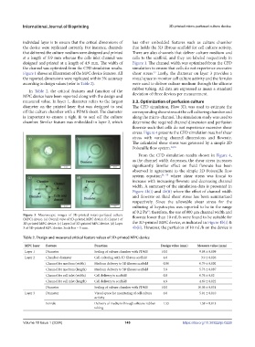
Figure 3. Macroscopic images of 3D-printed micro-perfused culture flowrate lower than 10 mL/h were found to be suitable for
(MPC) device. (a) Overall view of 3D-printed MPC device. (b) Layer 1 of
3D-printed MPC device. (c) Layer 2 of 3D-printed MPC device. (d) Layer the 3D-printed MPC device, as indicated in Figure 4b(i) &
3 of 3D-printed MPC device. Scale bar = 5 mm. 4b(ii). However, the perfusion of 10 mL/h on the device is
Table 2. Design and measured critical feature values of 3D-printed MPC device
MPC layer Feature Function Design value (mm) Measure value (mm)
Layer 1 Diameter Sealing of culture chamber with PDMS 10.0 9.98 ± 0.099
Layer 2 Chamber diameter Cell culturing with 3D fibrous scaffold 4.0 3.9 ± 0.026
Channel for medium (width) Medium delivery to 3D fibrous scaffold 0.80 0.79 ± 0.002
Channel for medium (length) Medium delivery to 3D fibrous scaffold 5.9 5.73 ± 0.087
Channel for cell inlet (width) Cell delivery to scaffold 0.8 0.76 ± 0.02
Channel for cell inlet (length) Cell delivery to scaffold 4.9 4.69 ± 0.022
Diameter Sealing of culture chamber with PDMS 10.0 10.06 ± 0.031
Layer 3 Diameter Visual space for monitoring of cell culture 6.0 5.91 ± 0.010
activity
Ferrule Delivery of medium through silicone rubber 1.55 1.59 ± 0.013
tubing
Volume 10 Issue 1 (2024) 149 https://doi.org/10.36922/ijb.0226