
Page 553 - IJB-10-3
P. 553
International Journal of Bioprinting Engineered 3D-printed PVA vascular grafts
increasing the degree of crosslinking or network density
and decreasing the degree of swelling.
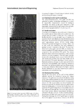
3.6. Poly(vinyl alcohol) graft morphology
The lysine-biofunctionalized PVA graft (3D-3H) was
subjected to surface morphology investigation to unveil
its support-like characteristics, crucial for biological
assessment. The surface of the graft displayed a rough
topography characterized by high irregularities and open
pores measuring approximately 4–10 μm (Figure 8).
3.7. Tensile evaluation
A mechanical investigation was performed to determine
the sample’s response when subjected to tensile stress. The
samples were pre-swollen in water for 1 h to induce the
flexible behavior of a vascular graft. Figure 9 displays the
response of both unmodified and lysine-biofunctionalized
PVA grafts. The unmodified PVA graft displayed a broad
yield region/plateau around 30–35% tensile strain,
followed by gradual propagation of sample failure. Up
to 30% strain, the unmodified PVA graft exhibited a
gradual increase in response to the strain. The maximum
stress in the yield region was 0.23 MPa. In contrast, the
biofunctionalized PVA graft exhibited a distinct behavior
compared to the unmodified PVA grafts. The sample
displayed a linear stress/strain dependency, with increased
resistance to stress propagation. The yield region was also
broad, with a maximum tensile stress of about 0.58 MPa.
The tensile stress at break was more than double that of
the unmodified PVA graft, displaying a linear response.
Biofunctionalization emerges as a key approach for both
enhancing biocompatibility and improving mechanical
properties. The biofunctionalized specimen demonstrated
a more elastic behavior, likely due to the higher network
density facilitated by new inter/intramolecular physical
interactions and chemical bonding.
3.8. Mechanical flow testing
Among the PVA grafts, 1D-3H and 3D-3H exhibited
sufficient stability for mechanical testing (for fatigue
resistance). The grafts were secured onto the platform using
acrylic resin, and the platform was then connected to both
the feeding glass (containing water) and the vacuum pump
(Figure 10). The vacuum pump was set to 40 mbar, and
the test commenced. The vacuum induced the fluid (water)
from the feeding glass to traverse the flexible hose and
reach the PVA graft through the 0.3 mm metallic channel.
The fluid passed through the PVA graft and exited via
the 0.8 mm metallic channel. Subsequently, the fluid was
Figure 8. Scanning electron microscope (SEM) images of the lysine- collected in the glass collector. To detect any fluid leakage,
functionalized poly(vinyl alcohol) (PVA) grafts. Magnification: (A) the platform was filled with water to cover the PVA graft.
400×; (B) 1000×; and (C) 5000×. Scale bars: (A) 200 µm; (B) 100 µm; and During fluid drainage, the 1D-3H graft began to fracture
(C) 20µm. due to the applied vacuum forces. However, the 3D-3H
Volume 10 Issue 3 (2024) 545 doi: 10.36922/ijb.2193