
Page 614 - IJB-10-3
P. 614
International Journal of Bioprinting Wireless module system applied on 3D-printed implant
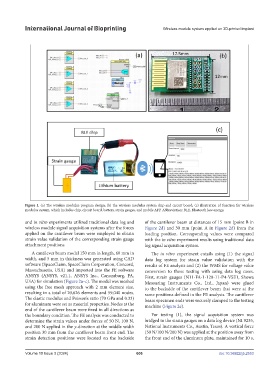
Figure 1. (a) The wireless modulus program design; (b) the wireless modulus system chip and circuit board; (c) illustration of function for wireless
modulus system, which includes chip, circuit board, battery, strain gauges, and mobile APP. Abbreviation: BLE, Bluetooth low energy.
and in vitro experiments utilized traditional data log and of the cantilever beam at distances of 15 mm (point B in
wireless module signal acquisition systems after the forces Figure 2d) and 30 mm (point A in Figure 2d) from the
applied on the cantilever beam were employed to obtain loading position. Corresponding values were compared
strain value validation of the corresponding strain gauge with the in vitro experiment results using traditional data
attachment positions. log signal acquisition system.
A cantilever beam model 150 mm in length, 60 mm in The in vitro experiment entails using (1) the signal
width, and 5 mm in thickness was generated using CAD data log system for strain value validation with the
software (SpaceClaim, SpaceClaim Corporation, Concord, results of FE analysis and (2) the WMS for voltage value
Massachusetts, USA) and imported into the FE software conversion to those testing with using data log cases.
ANSYS (ANSYS, v21.1, ANSYS Inc., Canonsburg, PA, First, strain gauges (N11-FA-1-120-11-P4-VSE1, Showa
USA) for simulation (Figure 2a–c). The model was meshed Measuring Instruments Co., Ltd., Japan) were glued
using the free mesh approach with 2 mm element size, to the backside of the cantilever beam that were at the
resulting in a total of 20,626 elements and 59,040 nodes. same positions defined in the FE analysis. The cantilever
The elastic modulus and Poisson’s ratio (70 GPa and 0.33) beam specimen ends were securely clamped to the testing
for aluminum were set as material properties. Nodes at the machine (Figure 2e).
end of the cantilever beam were fixed in all directions as
the boundary condition. The FE analysis was conducted to For testing (1), the signal acquisition system was
determine the strain values under forces of 50 N, 100 N, bridged to the strain gauges on a data log device (NI 9235,
and 200 N applied in the y-direction at the middle width National Instruments Co., Austin, Texas). A vertical force
position 30 mm from the cantilever beam front end. The (50 N/100 N/200 N) was applied at the position away from
strain detection positions were located on the backside the front end of the aluminum plate, maintained for 10 s,
Volume 10 Issue 3 (2024) 606 doi: 10.36922/ijb.2553