
Page 615 - IJB-10-3
P. 615
International Journal of Bioprinting Wireless module system applied on 3D-printed implant
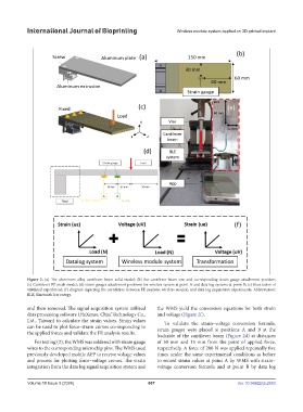
Figure 2. (a) The aluminum alloy cantilever beam solid model; (b) the cantilever beam size and corresponding strain gauge attachment position;
(c) Cantilever FE mesh model; (d) strain gauges attachment positions for wireless system at point A and data log systems at point B; (e) illustration of
validated experiment; (f) diagram depicting the correlation between FE analysis, wireless module, and data log acquisition experiments. Abbreviation:
BLE, Bluetooth low energy.
and then removed. The signal acquisition system utilized the WMS yield the conversion equations for both strain
data processing software (FleXense, Chief Technology Co., and voltage (Figure 2f).
Ltd., Taiwan) to calculate the strain values. Strain values To validate the strain–voltage conversion formula,
can be used to plot force–strain curves corresponding to strain gauges were placed at positions A and B at the
the applied forces and validate the FE analysis results.
backside of the cantilever beam (Figure 2d) at distances
For testing (2), the WMS was soldered with strain gauge of 30 mm and 15 mm from the point of applied force,
wires to the corresponding microchip pins. The WMS used respectively. A force of 200 N was applied repeatedly five
previously developed mobile APP to receive voltage values times under the same experimental conditions as before
and process for plotting force–voltage curves. The strain to record strain values at point A by WMS with strain–
integration from the data log signal acquisition system and voltage conversion formula and at point B by data log
Volume 10 Issue 3 (2024) 607 doi: 10.36922/ijb.2553