
Page 104 - IJB-5-1
P. 104
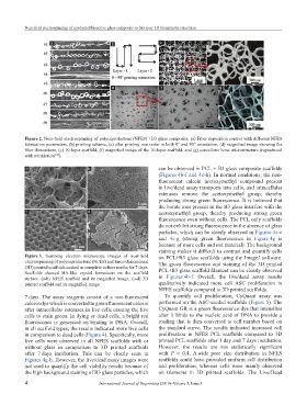
Near-field electrospinning of a polymer/bioactive glass composite to fabricate 3D biomimetic structures


                     a                      b                  c                  d


                                            e                  f                      g


           Figure 2. Near-field electrospinning of polycaprolactone (NFES) +B3 glass composite. (a) Fiber deposition control with different NFES
           fabrication parameters, (b) printing schema, (c) after printing one raster in both 0° and 90° orientation, (d) magnified image showing the
           fiber dimensions, (e) 10-layer scaffold, (f) magnified image of the 10-layer scaffold, and (g) cancellous bone microstructure (reproduced
           with permission ).
                      [16]
           a                       b                           can be observed in PCL + B3 glass composite scaffolds
                                                               (Figures 4b-f and 4d-h). In normal conditions, the non-
                                                               fluorescent  calcein  acetoxymethyl  compound  present
                                                               in live/dead assay transports into cells, and intracellular
                                                               esterases  remove  the  acetoxymethyl  group,  thereby
                                                               producing strong green fluorescence. It is believed that
                                                               the borate ions present in the B3 glass interfere with the
           c                       d                           acetoxymethyl  group,  thereby  producing  strong  green
                                                               fluorescence even without cells. The PCL only scaffolds
                                                               do not exhibit strong fluorescence in the absence of glass
                                                               particles, which can be clearly observed in Figures 4a-e
                                                               and  4c-g  (strong  green  fluorescence  in  Figure 4g  is
                                                               because of more cells and not material). The background
                                                               staining makes it difficult to contrast and quantify cells
           Figure 3.  Scanning  electron  microscope  images  of  near-field   on PCL+B3 glass scaffolds using the ImageJ software.
           electrospinning of polycaprolactone (NFES) and three-dimensional   The  green  fluorescence  and  staining  of  the  3D  printed
           (3D) printed scaffolds soaked in complete culture media for 7 days.
           Scaffolds  showed  HA-like  crystal  formations  on  the  scaffold   PCL+B3 glass scaffold filament can be clearly observed
           surface.  (a-b)  NFES  scaffold  and  its  magnified  image,  (c-d)  3D   in  Figures 4b-f.  Overall,  the  live/dead  assay  results
           printed scaffold and its magnified image.           qualitatively  indicated  more  cell  ASC  proliferation  in
                                                               NFES scaffolds compared to 3D printed scaffolds.
           7 days. The assay reagents consist of a non-fluorescent   To  quantify  cell  proliferation,  CyQuant  assay  was
           calcein dye which is converted to green fluorescent calcein   performed on the ASC-seeded scaffolds (Figure 5). The
           after intracellular esterases in live cells causing the live   CyQuant GR is a green fluorescence dye that intensifies
           cells to stain green. In dying or dead cells, a bright red   after  it  binds  to  the  nucleic  acid  of  DNA  to  provide  a
           fluorescence is generated on binding to DNA. Overall,   reading that is then converted to cell number based on
           in all scaffold types, the results indicated more live cells   the standard curve. The results indicated increased cell
           in comparison to dead cells (Figure 4). Specifically, more   proliferation  in  NFES  PCL  scaffolds  compared  to  3D
           live cells were observed in all NFES scaffolds with or   printed PCL scaffolds after 1 day and 7 days incubation.
           without  glass  in  comparison  to  3D  printed  scaffolds   However,  the  results  are  not  statistically  significant
           after  7 days  incubation.  This  can  be  clearly  seen  in   with  P  =  0.4.  A wide  pore  size  distribution  in  NFES
           Figures 4g-h. However, the live/dead assay images were   scaffolds could have provided uniform cell distribution
           not used to quantify the cell viability results because of   and  proliferation,  whereas  cells  were  mainly  observed
           the high background staining of B3 glass particles, which   on  filaments  in  3D  printed  scaffolds.  The  Live/Dead

           4                           International Journal of Bioprinting (2019)–Volume 5, Issue 1