
Page 26 - IJB-5-1
P. 26
Shuai C
bulk state. In addition, the melting point of Mg is very Zn powder easily causes a large amount of plume due
close to the boiling point. In spite of those, our research to the metallic vapor. The formed plume will change the
group explored the application of SLM to prepare porous optical properties of the laser beam, such as the beam
Mg with a home-made SLM system [123] . Under the profile and the energy density. These reduce the process
protection of Ar gas, an Mg scaffold was successfully stability and cause poor part quality. To address these
formed at optimized process parameters. Li et al. [124] issues, Grasso et al. [125] applied an in situ monitoring
also successfully prepared porous Mg alloy (WE43) approach to detect the unstable process behaviors and
scaffolds by SLM, as shown in Figure 6C. Mechanical anticipated severe defects in SLM of pure Zn. Besides,
tests revealed that the obtained Mg scaffolds exhibited some researchers explored the use of SLM to prepare
sufficient Young’s modulus of 700–800 MPa, which was bulk Zn for bone tissue repair [126-128] . However, to our
comparable to trabecular bone after biodegradation for best knowledge, there are few reports regarding SLM of
4 weeks. The Mg scaffolds showed a proper degradation Zn alloys scaffolds. Instead, a technique merging both
rate (20% volume loss after immersion for 4 weeks) and gravity casting and 3D printing achieved success in
good compatibility (level 0 cytotoxicity) (Figure 6D). As producing porous Zn scaffolds [129] .
for Zn and its alloys, the low melting and boiling points
also challenge their process stability in SLM. SLM of 3.3. FDM
A B
C
D E
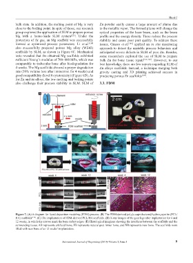
Figure 7. (A) A diagram for fused deposition modeling (FDM) process. (B) The FDM-derived poly(ε-caprolactone)/hydroxyapatite (PCL/
HA) scaffolds [139] . (C) The implantation of FDM-derived PCL/HA scaffolds. (D) X-ray images of the goat legs after implantation for 4 and
12 weeks, in which the arrows mark the bone defect edges. (E) Histological imagines showing the interfaces between the scaffolds and the
surrounding tissue. AB represents artificial bone, FB represents natural goat femur bone, and NB represents new bone. The scaffolds were
filled with new bone after 12 weeks’ implantation.
International Journal of Bioprinting (2019)–Volume 5, Issue 1 9