
Page 34 - IJB-5-2
P. 34
A novel inkjet system for live cell bioprinting
were seeded at a density of 2.5 × 10 cell/well in 24-well alginate as scaffold bioink 1; 100 mM calcium chloride
4
plates and cultured for 3 days. The average numbers (CaCl ) as scaffold bioink 2; 5 × 10 cells/ml NHDF cells
7
2
of colony-forming units were counted after staining stained with Cell Tracker Green and suspended in DPBS
with red alkaline phosphatase substrate kit (VECTOR and 0.5 wt% sodium alginate as cell-laden bioink 1; and
laboratories). For immunostaining, the cells were fixed 5 × 10 cells/ml NHDF cells stained with Cell Tracker
7
with 4% paraformaldehyde and incubated overnight Orange and suspended in DPBS and 0.5 wt% sodium
at 4°C with primary antibodies, Nanog (abcam) 1:200, alginate as cell-laden bioink 2. Printing was performed
SSEA-1 (abcam) 1:100, 2 h at room temperature with on a glass slide as follows: (a) A layer of sodium alginate
secondary antibodies, and 5 min with 1:10,000 Hoechst was deposited by ejecting scaffold bioink 1 using the first
33342 (Thermo Fisher Scientific). industrial head at 10 Hz, immediately followed by (b) a
layer of CaCl using the second industrial head for rapid
2
2.9. 3D Bioprinting System Setup gelling of a thin alginate hydrogel scaffold layer; (c) cell-
A bioprinting system has been designed as shown in laden bioink 1 was deposited with a cell-printing printhead
Figure 1B for constructing 3D tissues with multiple at 10 Hz to draw a 10 mm line along the X-axis; (d) a
cell types. The present system is equipped with newly hydrogel scaffold layer was superimposed onto the cell
developed cell-printing inkjet heads and commercial layer using the same procedure in (a) and (b); and (e) the
industrial inkjet heads for ejecting biomaterials. cell-laden bioink 2 was deposited with a cell-printing
A maximum of three cell-printing inkjet heads can printhead at 10 Hz to draw a 10 mm line along the Y-axis.
be mounted in parallel so that three types of cells The steps from (a) to (e) were repeated until a 10-layer
can be printed sequentially to develop tissues with construct was achieved. To observe the superposition of
heterogeneous patterns. The position of the nozzle is layers, cross-sectional Z-stack images of the multilayered
controlled horizontally on the X-axis and vertically constructs were acquired using a confocal laser scanning
on the Z-axis to allow the deposition of cells not only microscope (TCS SP8 STED CW, Leica Microsystems)
for surface patterning but also in three dimensions. at the intersection of the green and orange cell lines after
In addition, two industrial multi-nozzle inkjet heads fixation in ethanol.
(MH2420 Print Head, Ricoh) allow the successive
printing of two different liquids such as a hydrogel 3. Results
precursor and an appropriate cross-linking reagent,
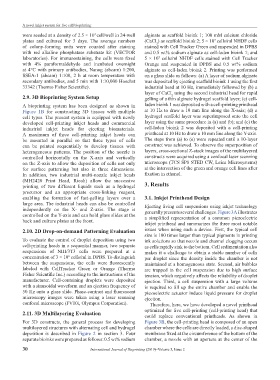
enabling the formation of fast-gelling layers over a 3.1. Inkjet Printhead Design
large area. The industrial heads can also be controlled Ejecting living cell suspensions using inkjet technology
independently on the X- and Z-axis. The stage is generally presents several challenges. Figure 3A illustrates
controlled on the Y-axis and can hold glass slides at the a simplified representation of a common piezoelectric
back and culture plates at the front.
inkjet printhead and summarizes the three most notable
2.10. 2D Drop-on-demand Patterning Evaluation issues when using such a device. First, the typical cell
size is 100 times larger than typical pigments in printing
To evaluate the control of droplet deposition using two ink solutions so that nozzle and channel clogging occurs
cell-printing heads in a sequential manner, two separate as cells rapidly sink to the bottom. Cell sedimentation also
suspensions of NIH/3T3 cells were prepared at a makes it a challenge to obtain a stable number of cells
concentration of 3 × 10 cells/ml in DPBS. To distinguish per droplet since the density inside the chamber is not
6
between the suspensions, the cells were fluorescently maintained at a homogeneous state. Second, air bubbles
labeled with CellTracker Green or Orange (Thermo are trapped in the cell suspension due to high surface
Fisher Scientific Inc.) according to the instructions of the tension, which negatively affects the reliability of droplet
manufacturer. Cell-containing droplets were deposited ejection. Third, a cell suspension with a large volume
with a sinusoidal waveform and an ejection frequency of is required to fill up the entire chamber and enable the
50 Hz onto a glass slide. Phase-contrast and fluorescent piezoelectric actuator induce liquid pressure for droplet
microscopy images were taken using a laser scanning ejection.
confocal microscope (FV10i, Olympus Corporation). Therefore, here, we have developed a novel printhead
optimized for live cell-printing (cell-printing head) that
2.11. 3D Multilayering Evaluation could replace conventional printheads. As shown in
For 3D constructs, the general process for developing Figure 3B, the cell-printing head is composed of an open
multilayered structures with alternating cell and hydrogel chamber where the cells are directly loaded, a disc-shaped
deposition is described in Figure 2 in section 3. Four membrane fixed at the circumference of the bottom of the
separate bioinks were prepared as follows: 0.5 wt% sodium chamber, a nozzle with an aperture at the center of the
30 International Journal of Bioprinting (2019)–Volume 5, Issue 2