
Page 40 - IJB-6-1
P. 40
Solvent-based extrusion 3D printing
A
B
C
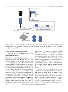
Figure 3. The schematic of ink flow inside the printing needle (A); the first layer of filament formation
on the substrate (B); the fusion process of two filament layers in the vertical direction within the printed
woodpile structure (C).
4 SBE 3D printed scaffold assessment investigated the relationship between filament
distance and diffusion rate (φ). Micro-computed
4.1 SBE 3D printed scaffold structure and tomography (micro-CT) can also be used to
mechanical properties evaluate the scaffold pore dimensions, porosity,
[11]
The solvents used in SBE 3D printing can cause and pore interconnectivity. Hockaday et al.
scaffold shrinkage after drying; shrinkage can performed surface deviation analysis by micro-CT
result in changes to the scaffold structural and imaging of SBE 3D printed valve scaffolds with
mechanical properties. The 3D printed scaffold inner diameters of 22, 17, and 12 mm. The results
structures need to be evaluated before use in vitro or of this study indicate that the printing accuracy
in vivo. There is no standardized method to quantify decreased as the scaffold geometric size was
the difference between the theoretical CAD design reduced.
and the printed structure. A common evaluation The SBE 3D printed scaffold should have
approach involves the measurement of the printed appropriate mechanical properties (e.g., stiffness)
filament diameter and the filament distance from that match with those of the host tissue. Natural
microscopy or SEM images. He et al. developed polymer and synthetic polymers are often
[19]
a method to measure the intersection area formed combined with bioactive materials to achieve
by filaments in microscopy images (Figure 4C). higher mechanical strength and better biological
They found that the area of the rectangle (A ) activity. Serra et al. fabricated scaffolds with two
[35]
Re
obtained from experiments was much smaller types of geometries using two groups of materials,
than the theoretical rectangle area (A ). They also namely PLA/PEG and PLA/PEG/bioactive CaP.
Rt
36 International Journal of Bioprinting (2020)–Volume 6, Issue 1