
Page 41 - IJB-6-1
P. 41
Zhang, et al.
A
B
C
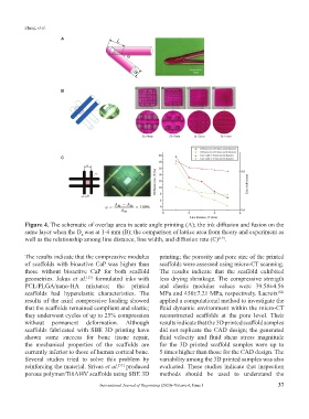
Figure 4. The schematic of overlap area in acute angle printing (A); the ink diffusion and fusion on the
same layer when the D was at 1-4 mm (B); the comparison of lattice area from theory and experiment as
L
well as the relationship among line distance, line width, and diffusion rate (C) .
[19]
The results indicate that the compressive modulus printing; the porosity and pore size of the printed
of scaffolds with bioactive CaP was higher than scaffolds were assessed using micro-CT scanning.
those without bioactive CaP for both scaffold The results indicate that the scaffold exhibited
geometries. Jakus et al. formulated inks with less drying shrinkage. The compressive strength
[13]
PCL/PLGA/nano-HA mixtures; the printed and elastic modulus values were 39.58±4.56
scaffolds had hyperelastic characteristics. The MPa and 450±7.21 MPa, respectively. Lacroix
[52]
results of the axial compressive loading showed applied a computational method to investigate the
that the scaffolds remained compliant and elastic; fluid dynamic environment within the micro-CT
they underwent cycles of up to 25% compression reconstructed scaffolds at the pore level. Their
without permanent deformation. Although results indicate that the 3D printed scaffold samples
scaffolds fabricated with SBE 3D printing have did not replicate the CAD design; the generated
shown some success for bone tissue repair, fluid velocity and fluid shear stress magnitude
the mechanical properties of the scaffolds are for the 3D printed scaffold samples were up to
currently inferior to those of human cortical bone. 5 times higher than those for the CAD design. The
Several studies tried to solve this problem by variability among the 3D printed samples was also
reinforcing the material. Srivas et al. produced evaluated. These studies indicate that inspection
[51]
porous polymer/Ti6Al4V scaffolds using SBE 3D methods should be used to understand the
International Journal of Bioprinting (2020)–Volume 6, Issue 1 37