
Page 30 - IJB-7-1
P. 30
3D Printing Technologies in Metallic Implants
density beam is utilized to melt and fuse the preferred melting process is engendered by the energy emission from
regions according to CAD data. After the completion of the electron beam of a tungsten filament which consists of
the first layer, the building platform is lowered, and the two magnetic coils for controlling the beam position and
subsequent layer of powder is deposited on the previous diameter and the adjustment of focusing and defocusing
[31]
layer before the laser beam begins to scan a new layer. conditions ; Figure 6B demonstrates a schematic
This procedure is repeated several times until the entire 3D presentation of the EMB device. Furthermore, Figure 8
part is fabricated. The completed 3D part is then removed represents the EBM chamber (Figure 8A) and the EBM
from the platform manually or by electrical discharge process steps (Figure 8B). In the EBM technique, each slice
machining (EDM) and the loose powders removed from is categorized in two distinct regions named contours and
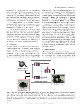
the surface . Figure 7 shows the schematic presentation squares. First, the contour region which acts as an interface
[25]
of the processing steps in the SLM technique. between the part and the surrounding powders is produced.
The key process variables of the SLM technique, Then, the square parts of the inner region of these boundary
such as scanning speed, laser power, hatch spacing, and contour zones are fabricated by EBM. Performing the
and layer thickness, must be accurately regulated. EBM process in the vacuum condition prevents impurity
Furthermore, some important physical aspects should be and contamination that leads to the formation of high-
considered, including thermal fluctuation in the material quality parts with good mechanical properties [32,33] . After
that will lead to crack initiation and failure, the balling the complete fabrication of a 3D printed object, the part is
issue that intervenes in continuous melt formation, and kept inside the chamber for cooling. Then, excess powders
the absorptivity of material toward laser irradiation . are removed from the part, and because of the relatively
[25]
rough surface of the EBM parts [34,35] , they are subject to
(2) EBM method final surface treatments through milling, turning, polishing,
[36]
The EBM method, as one of the layer-by-layer techniques, and grinding devices .
is among the most used AM techniques. It can be used to 2.3. Binder jetting
produce high-quality metal and metallic alloys parts [27-29]
and the near net shape metallic samples with complex The binder jetting-based techniques, also known as the
geometries . In this method, the structures are made direct 3DP, use the inkjet printing system. Specifically,
[30]
by selective melting of discrete powder layers through the printer head in this system not only moves in the
electron-beam gun under the vacuum condition. The x-y plane as the conventional state but also runs in the
Figure 7. Schematic representation of the processing steps in the selective laser melting (Reprinted from International Journal of
Refractory Metals and Hard Materials, Volume 77, Sing SL, Wiria F E and Yeong WY, Selective laser melting of titanium alloy with
50 wt% tantalum: Effect of laser process parameters on part quality, pp 120-127, Copyright (2018), with permission from Elsevier) .
[26]
The powder mixture is added into chamber and then the laser scanned and fused the powders according to the sliced computer-aided
design data. Subsequently, the cycle of powder deposition, laser irradiation, and lowering the tray is repeated until the entire 3D part is
produced.
26 International Journal of Bioprinting (2021)–Volume 7, Issue 7