
Page 112 - IJB-7-2
P. 112
Technique of Thyroid Cartilage Scaffold Support Formation
A B C
D E F
G H
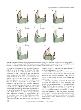
Figure 4. Assessment of wall thickness of the support and optimization options. (A-C) Areas with thickness <0.52 cm for options with 0.5,
2.0, and 8 mm slice step, respectively. (D-G). The result of procedures 1, 2, and 3 applying the support with 2.0 mm step (b). (H). Areas with
thickness <1.03 cm for the support with 2.0 mm step underwent double modification according to procedure 1 (g).
The maximal values for the first two parameters were change is shown by arrows) was satisfactory and did not
512. Thus, the used values (96, 128, and 512 units) result in complication of the model.
referred to 19, 25, and 100%. According to the table, It should be noted that all these procedures were not
procedures 1 and 3 included a minimal thickness accompanied by the change in volume of the support. The
value requirement that fitted nozzle diameter (two decrease in this parameter for Figure 4D-G was 0.90,
nozzle diameters in the case of procedure 2). The 0.80, 0.95, and 1.10% of the initial model (Figure 4B),
value of “Solid accuracy” in the case of procedure 3 respectively.
also fitted diameter of a nozzle (96 units–0.517 mm). Depending on printing parameters, the problem of
The data obtained are presented in Figure 4D-F. All excessively thin walls may be almost unsolvable. The
approaches have improved wall thickness. Procedure areas of wall thickness model of <1.03 mm are shown in
2 led to undesirable overlap between the support and
thyroid cartilage scaffold. Procedure 3 resulted in the Figure 4H. These data are important for printing of the
unreasonable complication of the model (the number of scaffold with supports on a small scale (e.g., 1:2), or in the
polygons increased by 15 times). It could be assumed case of non-standard printing parameters (e.g., material
that a slight decrease in “Mesh density” parameter output, and fill density). Both events were investigated
would reduce the complexity of the support but will in this study. An additional application of the procedures
not contribute to the issue of wall thickness. Another for wall thickness optimization was impossible since this
optimization option was considered. Procedure 1 was would inevitably entail critical changes in the geometry
reapplied (Figure 4G). The effect (the most pronounced of the support.
108 International Journal of Bioprinting (2021)–Volume 7, Issue 2