
Page 215 - IJB-8-4
P. 215
Dong, et al.
and static conditions, the load was gradually applied to designed scaffold models were put into Photo Workshop
the limit and the compressive strength was evaluated. software in STL format and then the printing parameters
Maximum equivalent stress was obtained under the were adjusted. A schematic diagram about its principle
same process parameters, 2.11 MPa and 0.19 MPa is shown in Figure 2B. The ultraviolet (UV) light was
corresponding diagrams are shown in Figure 1C. The emitted by the LCD array and homogenized by the lens
stimulated result indicated that the mechanical properties array. When the LCD screen displayed the mask, the inner
of scaffold B were superior to that of scaffold A. liquid crystal of the mask region rearranged to allow the
UV light to pass through. The designed scaffold models
2.2. LCD mask stereolithography printing and were output in STL format after modeling. In the printing
slurry preparation process, a layer thickness of 0.06 mm, 4-s exposure
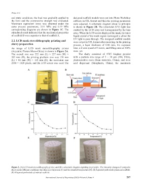
An image of LCD mask stereolithography printer time, a Z-axis speed of 3 mm/s, and filling rates at 100%
(Anycubic Photon Mono-China) is shown in Figure 2A. were set.
The overall size was 222 mm (L) × 227 mm (W) × The slurry consisted of 45S5 bioglass powder
383 mm (H), the printing platform size was 130 mm with a particle size range of 5 – 30 μm (3M, USA),
(L) × 80 mm (W) × 165 mm (H), the resolution was photosensitive resin (Esun materials, China), and oleic
2560 × 1620 pixels, and 2K LCD screen was used. The acid dispersant (Sinopharm, China); the maximum
A B
C D
E F
Figure 2. (A) LCD mask stereolithography printer, and (B) a schematic diagram depicting its principle. The viscosity changes of composite
slurry under different conditions: the oleic acid dispersion (C) and the reheated temperature (D). (E) A printed perforated cylindrical scaffold.
(F) A layered perforated cylindrical scaffold.
International Journal of Bioprinting (2022)–Volume 8, Issue 4 207