
Page 216 - IJB-8-4
P. 216
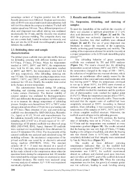
3D Printed Porous 45S5 Bioceramic
           percentage  content  of  bioglass  powder  was  40  wt%.   3. Results and discussion
           Specific processes were followed. Bioglass and resin in a
           ratio of 40:60 were mixed and stirred under planetary ball   3.1. Suspension, debinding, and  sintering of
           mill for 8 h to obtain the compound solution. The ball mill   samples
           rotation speed was 300 rom. Then, different proportion of   To meet the formability of the scaffold, the viscosity of
           oleic acid dispersant was added, stirring was continued   slurry  was  adjusted  to  optimum  proportions  of  2  wt%
           mechanically for 10 min, and the viscosity was adjusted   oleic acid dispersant at 50°C (Figure 2C and D). The
           in order to process molding. The composite slurry was   45S5  bioglass  was  uniformly  dispersed  in  the  resin
           put into a water bath, heated to reduce its viscosity, and   solution;  therefore,  two  ideal  scaffolds  were  obtained
           then put into the LCD mask stereolithography printer to   (Figure  2E and F).  The  use  of  good  dispersant  was
           fabricate the scaffolds.                            beneficial  to  reduce  the  viscosity  of  the  suspension,
           2.3. Debinding sinter and sample                    thereby achieving good homogeneity and mobility. The
                                                               casting of the suspensions allowed for suitable viscosity at
           characterization                                    a proper temperature in the LCD mask stereolithography
           The printed green scaffolds were put into muffle furnace   process [35,36] .
           for  debinding  sintering  with  different  heating  rates  of   The debinding behavior of green composite
           0.5°C/min,  1°C/min,  2°C/min.  When  the  temperature   scaffolds  was  evaluated  by  TG  and  DTG  analyses
           reached  at  100°C,  200°C  and  300°C,  the  temperatures   (Figure  3A).  The  results  showed  that  the  debinding
           were  hold  for  60  min,  while  the  temperature  reached   temperature occurred between 200°C and 550°C. When
           at  400°C  and  500°C,  the  temperatures  were  hold  for   the temperature changed in the range of 100 – 300°C,
           120  min,  respectively.  After  debinding,  sintering  rate   the reduction of weight loss rate was not obvious, which
           was 5°C/min. The maximum sintering temperatures were   indicates  an  endothermic  effect  mainly  caused  by  the
           1000°C, 1100°C, and 1200°C, and the temperatures were   evaporation of free water and some small molecules with
                                                                              [37]
           sustained for 120 min. Finally, the samples were cooled   low  melting  point . When  the  temperature  continued
           in the furnace at room temperature.                 to  rise  up  to  about  383°C,  the  DTG  curve  showed  an
               The  microstructure  formed  during  3D printing,   obvious  weight  loss  peak,  and  the  weight  loss  rate  of
           debinding,  and  sintering  process  was  recorded  using   green scaffolds reached the maximum and the pyrolysis
           a  Leica  camera  (Germany).  The  thermal  stability  of   rate of photosensitive resin reached the highest point
           sintered  samples  was  evaluated  by  thermogravimetric   (0.1%/°C). When the temperature reached above 550°C,
           (TG) and differential thermogravimetric (DTG) analyses   the weight of samples was basically stable. These results
           so as to measure  the change  temperature  of debinding   indicated  that  the  organic  resin  of  scaffold  had  been
           process. Samples were heated from 30°C to 700°C under   completely  removed  at  550°C.  According  to  thermal
           nitrogen atmosphere (flow of 25 mL/min) at a heating rate   analysis, when debinding, it was necessary to keep the
           of 10°C/min. Phase structure of pre- and post-sintering   temperatures of the samples at 300°C, 383°C and 550°C
           scaffolds was determined by XRD (MAXima, Shimadzu   to  obtain  complete  scaffold  structure.  Otherwise,  the
           Co., Japan) at 40 kV, 30 mA with monochromatic Cu-  scaffold would collapse in the debinding process.
           Kα radiation, typically with scan speed of 0.5°/min and   Based on the  TG and DTG analyses, the heating
           sampling pitch of 0.03° in a 2θ scale region of 10 – 65°.   rates  of  debinding  were  set  to  2°C/min,  1°C/min,  and
           Morphology of 3D printed scaffolds was observed using   0.5°C/min  and  the  temperature  was  sustained  at  every
           SEM (JSE-6700F, JEOL, Japan). Sintered 3D scaffolds   temperature gradient (Figure 3B). The results indicated
           were scanned and reconstructed in three dimensions by   that the heating rate was very high (2°C/min, 1°C/min),
           micro-CT (Quantum GX, USA). The true porosity of the   leading to the collapse of scaffolds, and when the heating
           sintered scaffolds was analyzed and calculated using 3D   rate  was  slowed  down  to  0.5°C/min,  scaffolds  were
           modeling software. The mechanical compression of the   completely debinded and their integrity were maintained
           printed  scaffolds  was  tested  by  an  electronic  universal   by Van der Waals force (Figure 3C).
           testing  machine  (INSTRON,  USA).  The  standard       The  results  at  three  different  sintering
           cylinder  (Ф  15  ×  15  mm)  was  stressed  at  a  speed  of   temperatures  indicated  that:  (i)  the  scaffold  had
           0.1 mm/min. The maximum compression stress described   completely collapsed at 1000°C; (ii) when the sintering
           in this study referred to the compression stress when the   temperature  was  1100°C,  the  scaffold  experienced
           specimen broke during the compression test. All samples   almost  no  collapse  and  showed  good  pore  structure;
           were tested and the average values are expressed as mean   and (iii) while at 1200°C, part of the scaffold deformed
           ±  standard  deviation.  The  results  were  analyzed  using   and shrunk greatly (Figure  3D).  When  the  sintering
           two-way analysis of variance. A P < 0.05 was considered   temperature was too low, the growth of ceramic grains
           statistically significant.                          was  not  sufficient,  leading  to  weak  bonding  among

           208                         International Journal of Bioprinting (2022)–Volume 8, Issue 4